Continue to Site

Welcome to EDAboard.com

Welcome to our site! EDAboard.com is an international Electronics Discussion Forum focused on EDA software, circuits, schematics, books, theory, papers, asic, pld, 8051, DSP, Network, RF, Analog Design, PCB, Service Manuals... and a whole lot more! To participate you need to register. Registration is free. Click here to register now.

viewing drill hole diameters in GC-prevue gerber viewer?

Status
Not open for further replies.
T

treez

Guest
Newbie level 1
Hello,
Do you know how I can view drill hole sizes in GC-Prevue gerber viewer.....I mean I have all the gerbers, but can't see how to get the drill hole diameters. So, ihave the drill file gerber, but how do I get the hole diameter in gc-prevue?
 

Hi,

the drill holes usually are not in the gerber files. (maybe your layout software can generate gerber files with drill holes included in the pads. Usually pcb manufacturers don´t want the drill holes)

There are additional drill files. Like SM3000. often you need an extra drill configuration (-file).

I didn´t use this for years. But i find it somehow difficult to do the drill setup. With newer versions of GCP it may be easier.


Klaus
 
  • Like
Reactions: treez

    T

    Points: 2
    Helpful Answer Positive Rating
You may not have a drill file Gerber, it is more likely to be an excellon NC drill file.

Import it into GC_Prevue as a drill layer, then it shows the holes.

But you must use the correct import settings.
 
  • Like
Reactions: treez

    T

    Points: 2
    Helpful Answer Positive Rating
Thanks,
Ive tried it but I cant get the drill holes over the gerber files....it shows the drill holes top right, and then the gerbers are on a different scale down in the bottom left.
Is there any software that allows us to view say the top copper gerber (RS274X) , and the excellon drill holes aswell?...so that we can check the drill hole diameters, and the restring (annulus) widths?
 

GVPrevue usually needs import settings to know about the drill file and embedded tool table scaling which are asked during NC import. I think, the operation is straightforward.

At worst case, you may have generated gerber and drill data with different origin, so you must apply an offset to get them matched in the gerber tool.

PCB manufacturers CAM operators have to be really creative to decode all kinds of odd gerber data obtained from the customers, so you rarely hear a complaint from their side as long as the data are complete. Nevertheless it's good practice to make gerber and drill data wide same origin and scaling (metric, IMHO) and of course use extended gerber/NC formats with embedded tool table.

If you tell us your settings, or better send example gerber and drill files, we can most likely help you with the required GCPrevue import settings.
 
  • Like
Reactions: treez

    T

    Points: 2
    Helpful Answer Positive Rating
Thanks,
In fact I have attached the complete gerbers (RS274X) and excellon drill file here.
It would be great to be able to view gerbers and drill holes at the same time.
 

Attachments

  • gerbers.zip
    218.4 KB · Views: 134

Strangely I got correct import with most recent GCPrevue 23.2.6. or older (2006) GCPowerstation 6.3.2 by just selecting all files under import.


Attachments

  • GWK1.zip
    360.7 KB · Views: 141
  • Like
Reactions: treez

    T

    Points: 2
    Helpful Answer Positive Rating
Thanks, just got it fine with free trial version of GC Power station, however the trial only lasts for 15 days.
The Graphicode website wouldn't give a free trial of gc prevue, probably because it detected my old free trial that's expired.
The graphicode website has no price info, so I emailed them, but I expect it is unaffordable.
 

I used GCPowerstation because it's my standard tool for Gerber data edition and panel assembly. But as said, free GCPrevue 23.2.6 works as well.

You didn't say which version brought up the problems you are describing in this thread,
 
  • Like
Reactions: treez

    T

    Points: 2
    Helpful Answer Positive Rating
GCprevue is free and available to all at https://www.graphicode.com/GC-Prevue#download

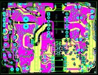
WHat software was that board made with? Those copper shapes look horrible.

When creating the Gerbers your probably using a setup for a photoplotter.
When creating NC drill data in Excellon format your probably using an NC machine setup.

If they both have different bed sizes and you always centre the data on the bed - then the centres are in different locations & GC-prvuse shows them offset.
An easy fix in either software.
 
  • Like
Reactions: treez

    T

    Points: 2
    Helpful Answer Positive Rating
It was made in eagle pro....I don't really care what the shapes look like, just that they do their job of thermal spreading...I find eagle is the quickest to bang in thermal copper pours....its very easy and quick, I just slap 'em in by the shedload, its then quick to assign it to a net, put a clearance in, and then a "rank" aswell, so it knows who's properties to "listen" to.

I found the copper pouring in altium was much longer and more awkward than in eagle pro........I also don't remember it being easy , or any less awkward in any of the other high-end packages that I used...it was awkward in altium, as you had to keep trying to grab a "point" where the pour could be moved from, and resizing or shaping it was a real problem.....eagle is great for smps type thermal pours
 

I preferred to "overlook" the copper shape appearance, I believe Eagle can perform better.

There may be no actual problem in using the layout for production, but I won't dare to present it to a custormer.
 
  • Like
Reactions: treez

    T

    Points: 2
    Helpful Answer Positive Rating
yes , but as you know is true, I would tell a customer that with a smps, its not the appearance, its the actual "Physics" of the layout that matters
 

Status
Not open for further replies.

Part and Inventory Search

Welcome to EDABoard.com

Sponsor

Back
Top