Continue to Site

Welcome to EDAboard.com

Welcome to our site! EDAboard.com is an international Electronics Discussion Forum focused on EDA software, circuits, schematics, books, theory, papers, asic, pld, 8051, DSP, Network, RF, Analog Design, PCB, Service Manuals... and a whole lot more! To participate you need to register. Registration is free. Click here to register now.

verilog combinational code

Status
Not open for further replies.

catalin560

Junior Member level 2
Joined
May 23, 2016
Messages
23
Helped
0
Reputation
0
Reaction score
0
Trophy points
1
Activity points
191
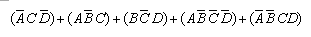
Hello! So I have the next assignment: write a verilog code for a combinational circuit that have the next values:
Code:
input     output
0-0-0 > 0
0-0-1 > 1 
0-1-0 > 1
0-1-1 > 0
1-0-0 > 1
1-0-1 > 0
1-1-0 > 0
1-1-1 > 1

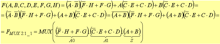
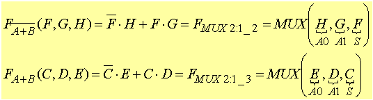
can this be done with a 3:1 mux with two selections?
 

Why a mux? Straightforward HDL, e.g. Verilog, way is writing a behavioral code and let the tool find the logic implementation.

If you "see" the implemented logic function, you can write it down directly, but need to prove the equivalence.
 

like this?

Code Verilog - [expand]
1
2
3
4
5
6
7
8
9
module ex (in,q);
input [2:0] in;
output reg q;
always @(in)
case (in)
3'b000: q=0;
3'b001: q=1;
...
endcase

 
Last edited by a moderator:

yes, your code is right (Behavioural model). But why can't you write it in more simple way.
If you see the logic, it is nothing but Ex-or of all the bits. output is '1' when you have odd no. of 1's in input.

you can simply write an assign statement (don't make q as reg)
assign q = ^in;

Regards,
Ashish
 
yes, your code is right (Behavioural model). But why can't you write it in more simple way.
If you see the logic, it is nothing but Ex-or of all the bits. output is '1' when you have odd no. of 1's in input.

you can simply write an assign statement (don't make q as reg)
assign q = ^in;
True in this case. I also agree that it's good if you can recognize the logic behind the table in post #1.

The purpose of behavioral coding is however to free you from doing manual logic minimization. The exercise problem can be put in two ways:
- learn to minimize logic (not particularly a Verilog theme)
- learn to write behavioral code
 

The purpose of behavioral coding is however to free you from doing manual logic minimization.

Agree with you. But small logic which can be identified easily, needn't to go trough n lines of code. It increases the readability of code. Also it shows the effectiveness of the designer to minimise the logic.
The another reason why I have pointed this because catalin560 asked in post#1 that "can this be done using 3:1 mux with two selections?" . I don't understand what kind of logic catalin560 is looking for by using 3:1 mux while it can be done by using simply an Ex-or gate or using 8:1 mux with 3 selections (behavioral model).
 

I neither understood the 3:1 mux question. To be used as two-input LUT, is must be a 4:1 mux. A 4:1 mux and an inverter can mimic the required logic.

But I guess this is no "logic circuit tricks" exercise.
 

like this?
module ex (in,q);
input [2:0] in;
output reg q;
always @(in)
case (in)
3'b000: q=0;
3'b001: q=1;
...
endcase

yep, this is all you need.
other posters mentioned that a XOR would also work, as long as you understand what they mean, you are good.
 
I tried simulating on iverilog.com but I got an error when trying to assign q = ^in however the other code worked just fine. I just realized that I can't use a mux because the exercise was strictly about a 3:1 combinational circuit with a,b,c as in and q as out...

Anyway... does anyone remember how to solve logic functions based on 2:1 mux?


This is an example I have from class but I just can't figure how to apply it to the above function...


This is my guess:
!A*(!B*C*D + C*!D) + A*(!B*C + !B*!C*!D) + (B*!C*D)
but I don't know if its right and from here I have no idea how to continue... can someone please give me a hint?
 

ok so what if:
C*(!A*!D+A*!B+!A*!B*D) + !C*(B*D+A*!B*!D)
for C A0 is !D+!B*D and A1 is !B and for !C A0 is A*!B and A1 is B
can someone confirm this?
 

How do you want to get the output?

1. Write a behavioral RTL in Verilog?
2. Write a structural RTL in Verilog?
3. Use a Karnaugh Map to solve the problem/get the output?
4. Use a 3:1 MUX (really 3:1 mux !!!?) or 2:1 MUX to solve the problem?

Make up your mind and stick to one!
 

I tried simulating on iverilog.com but I got an error when trying to assign q = ^in however the other code worked just fine. I just realized that I can't use a mux because the exercise was strictly about a 3:1 combinational circuit with a,b,c as in and q as out...

I just tried the code below and it works fine on iverilog.com (which seems to be using iverilog as the backend), weird site that links to some girl with odd videos :-?

Code Verilog - [expand]
1
2
3
4
5
6
7
8
module main;
  reg [3:0] in = 4'b1011;
  assign out = ^in;
  initial begin
    $display("in = %b, out = %b", in, out);
    $finish;
  end
endmodule

 
  • Like
Reactions: catalin560

    catalin560

    Points: 2
    Helpful Answer Positive Rating
    V

    Points: 2
    Helpful Answer Positive Rating
I tried simulating on iverilog.com but I got an error when trying to assign q = ^in however the other code worked just fine. I just realized that I can't use a mux because the exercise was strictly about a 3:1 combinational circuit with a,b,c as in and q as out...

Anyway... does anyone remember how to solve logic functions based on 2:1 mux?


This is an example I have from class but I just can't figure how to apply it to the above function...


This is my guess:
!A*(!B*C*D + C*!D) + A*(!B*C + !B*!C*!D) + (B*!C*D)
but I don't know if its right and from here I have no idea how to continue... can someone please give me a hint?

I tried to fit it in the standard equation of a mux !S*I0+S*I1
so here it goes
!A*(!B*C*D + C*!D) + A*(!B*C + !B*!C*!D) + (B*!C*D)
=> !A*(!B*C*D + C*!D + B*!C*D) + A*(!B*C + !B*!C*!D + B*!C*D)
=> !A* [!C(B*D) + C(!BD + !D)] + A* [!C(!B*!D + B*D) + C(!B)]
=> !A* [!C (!D*0 + D*B) + C !(!D*0 + D*B)] + A*[!C (!D*!B + D*B) + C (!B)]
=> !A* [!C*(MUX1) + C*not1(MUX1)] + A*[!C*(MUX2) + C*not2(B)]
=> !A*MUX3 + A*MUX4
=> MUX5

so basically it can be done by using five 2:1 Muxes and 2 inverters (assuming inverters available).

MUX1 => select line D with inputs GND(or D itself) and B
MUX2 => select line D with inputs (inverted B) and B
MUX3 => select line C with inputs MUX1 output and (inverted MUX1 output)
MUX4 => select line C with inputs MUX2 output and (inverted B)
MUX5 => select line A with inputs MUX3 output and MUX4 output

Two not gates (inverter) are required for B and MUX1 output.

There can be many ways to implement it, I don't know if this is the minimized logic.
Also I have a question to all, is there any way to implement a not gate using 2:1 Mux?
 
Also I have a question to all, is there any way to implement a not gate using 2:1 Mux?

Yes, very easily........

Code:
1 --|\
    | |--output = not(I)
0 --|/
     |
  input = I
 

Yes, very easily........

Code:
1 --|\
    | |--output = not(I)
0 --|/
     |
  input = I

Hi dpaul,

Thanks for the reply. But I forgot to frame the full question.

Is there any way to implement a not gate using only 2:1 Mux (without using supply 1(VCC) or 0(GND)) ?
 

Is there any way to implement a not gate using only 2:1 Mux (without using supply 1(VCC) or 0(GND)) ?


A 2:1 Mux is a device which has 3 i/p's and 1 o/p. You can't keep any i/p pins floating.
A NOT gate has 1 i/p and 1 o/p.

How will you do that? Think about again what you are asking!
 
Last edited by a moderator:
  • Like
Reactions: FvM

    FvM

    Points: 2
    Helpful Answer Positive Rating
You are hijacking the OP's thread. If you have your own Q's start your own thread.
You may receive infractions from Moderators for not following the rules.
I actually don't mind... we are all here to learn... having non-sense rules will only hurt the community and I've already been warned for some stuff that made my head hurt... so I decided to just ignore the warnings...

Do not ignore warnings or infractions. The rules are there for a reason as many have abused the forum with excessive thank you posts, lack of syntax tags with 1000 line posts (due to posting their code directly into the post without tags) Tags make posts readable and reduce the length of a post, posts in wrong sections just annoy users in that section and or get completely ignored as it is not the topic of that section, etc.

I'm closing this thread and have deleted some of the following posts as they do not contribute to the thread topic or offshoot topics that have been brought up.
 

Status
Not open for further replies.

Part and Inventory Search

Welcome to EDABoard.com

Sponsor

Back
Top