Continue to Site

Welcome to EDAboard.com

Welcome to our site! EDAboard.com is an international Electronics Discussion Forum focused on EDA software, circuits, schematics, books, theory, papers, asic, pld, 8051, DSP, Network, RF, Analog Design, PCB, Service Manuals... and a whole lot more! To participate you need to register. Registration is free. Click here to register now.

Vctrl of VCO in PLL, so strange!

Status
Not open for further replies.

lifusu

Newbie level 5
Joined
Dec 18, 2009
Messages
10
Helped
0
Reputation
0
Reaction score
0
Trophy points
1,281
Activity points
1,331
hi guys!
i design a pll (verilogA), 12MHz input , C2=400p, C1=40p, R2=3.3k,bandwidth=600k,Kvco=600MHz/v,Icp=20uA,when locked , the wave of Vctrl is as follows, why the Vctrl like this? i don't think it is ripple.
But when i delete divider, this condition will not occur, but the divider is ideal , why?
thx in advance!
pll.png
vc.png
vc2.png
 
Last edited:

another Q.
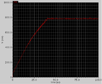
when i set the Vctrl 0v initially, the wave is as Fig.1;
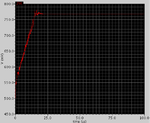
when i set the Vctrl 0.5v initially, the wave is as Fig2.


0v.png
0.5v.png
 

I don't know the software you are using but I would suggest you adjust the simulator settings - the erratic results look like timestep problems. Reduce the value of the maximum timestep.

Keith
 
  • Like
Reactions: lifusu

    lifusu

    Points: 2
    Helpful Answer Positive Rating
are you using any initial condition for your rc filter. try to use some 0.5Vlts to your filter as initial voltage.
Show us the AC response of your model.
 

I am using spectre and just as you said, it is really timestep problems! Thank U so much!
and also thank varunkant2k!
 

Status
Not open for further replies.

Similar threads

Part and Inventory Search

Welcome to EDABoard.com

Sponsor

Back
Top