faizalism
Member level 4
Hi to all,
I have problem simulating VCO gain. Actually I simply change Vcont and see the output frequency. So my result will be like , 1.8V - 4GHz, 1.6V - 3.8GHz, 1.4V - 3.6V .... . I used ring oscillator same as Savoj paper: 10Gb/s Half-Rate Phase Detector. But the problem is, his VCO curve (gain) is something like this ....
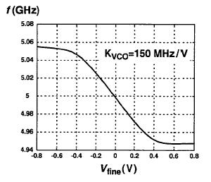
How he can get Vcont (Vfine) positive and negative numbers?
Thanks in advanced.
I have problem simulating VCO gain. Actually I simply change Vcont and see the output frequency. So my result will be like , 1.8V - 4GHz, 1.6V - 3.8GHz, 1.4V - 3.6V .... . I used ring oscillator same as Savoj paper: 10Gb/s Half-Rate Phase Detector. But the problem is, his VCO curve (gain) is something like this ....
How he can get Vcont (Vfine) positive and negative numbers?
Thanks in advanced.