Continue to Site

Welcome to EDAboard.com

Welcome to our site! EDAboard.com is an international Electronics Discussion Forum focused on EDA software, circuits, schematics, books, theory, papers, asic, pld, 8051, DSP, Network, RF, Analog Design, PCB, Service Manuals... and a whole lot more! To participate you need to register. Registration is free. Click here to register now.

Vce sat protection in IGBTs

Status
Not open for further replies.

7rots51

Advanced Member level 4
Joined
May 17, 2002
Messages
1,183
Helped
25
Reputation
50
Reaction score
12
Trophy points
1,318
Activity points
9,636
I want to protect IGBT from short circuit protection using Vcesat ,I want to use HCPL-316J optocouplers.


My IGBTs are 1200V,100A.

My question is :

Vcesat turn off IGBT when Vce reaches to about 8V when current of IGBT rises,but accorcing to Ic-Vce curve of IGBTs at currents 2x to 5x of nominal current Vce become about 4V,so how protection circuit protect IGBT? It beed 8V for protection!

Please clear this concept for me.
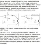
 

Drivers with Vcesat detection are able to handle a limited number of short circuit events. Disconnecting a short circuit involves massive stress for the device and will still cause devices failure if repeated too often. The drivers are unable to detect regular overload, e.g. double Ic. You need to implement current measurement to recognize overload conditions. In some cases chip temperature monitoring may fill the gap.
 

A new two-step gate drive circuit has been proposed which protects the IGBT during short circuit and over load fault. The gate-drive safely turns-off the IGBT in two steps. The IGBT stress during short circuit or fault current conditions is minimized. The new gate drive circuit can safely shut-off IGBTs with SCWT as low as 3usec.

It seems to be an elaborate method to clamp the gate just below threshold for soft turn off. http://www.evdl.org/docs/igbt_shortoff.pdf
 

SunnySkyguy:
A new two-step gate drive circuit has been proposed which protects the IGBT during short circuit and over load fault.
Is there any IC for this type of driver?(the circuit given in PCB is discrete)?

FvM:
Drivers with Vcesat detection are able to handle a limited number of short circuit events

Yes, I agree with you,I want to use Vcesat protection(like as the one is in HCPL-316J ) for shoot through protection and short circuit protection,but I want to add current sensors like as LEM current sensors to sense the current and prevent overload in load line ,..,is this a better way? is there any problem in this method?
for an H bridge welding application how many current sensor and at what locations are needed?
 

A single current sensor for the primary transformer current should be usually suffcient.

ST TD350 is e.g. implementing two-step turn off.
 
ocp.jpg\ref https://www.bodospower.com/restricted/downloads/bp_2012_08.pdf
 
FvM
A single current sensor for the primary transformer current should be usually suffcient.
Thanks for your notes , How to protect my H bridge from shoot through? Is Vcesat enough? or use current sensor (LEM LA series)?

- - - Updated - - -

FvM
A single current sensor for the primary transformer current should be usually suffcient.
Thanks for your notes , How to protect my H bridge from shoot through? Is Vcesat enough? or use current sensor (LEM LA series)?

- - - Updated - - -

SunnySkyguy
ocp.jpg\ref http://www.bodospower.com/restricted...bp_2012_08.pdf

what page number you mean?
thanks for your note.
 

A correctly designed driver circuit is the usual way to protect against shoot-through. Massive cases can be detected by Desat circuit.
 

A friend of mine blew his H bridge driver with rare earth magnet brought close to large diameter air coil. Cross-conductance (shoot-thru) was likely cause. Creating dead band switching with turning off both drivers before commutation is the solution in driver.

But I am not sure how much dead time is enough for variable inductance loads unless current sensing is done.

Most bridge driver specs are rated for time response on linear R loads only. Similar problem to overload on Vsat but due to transient load, rather than short circuit.
 

I want to use 4 HCPL-316 with MINMAX or 3 MORNSUN DC/DC for H bridge IGBT driver and Use LA100 LEM load current sensor for overcurrent and dead time control.
My application is seam welding and the load max current is known.Is there any other note?
My bus DC voltage is 550VDC and load average current is 30~40A (60-70A peak) and my IGBTs are 1200VDC/100A.
 

The LA100 LEM only has 500KHz bandwidth and seam welding with low resistance joints and plasma interface contacts give rise times in nS range not uS. If you want more accurate instrumentation on the power dissipation in each joint, you need wider bandwidth current sensing. You may want to calibrate the shunt with small pulses at various rates to check the transfer function for Q of resonance and characterize spectrum of seam welds with a shorted probe to a spectrum analyser > 50MHz.

Also the parallel resistance of previous welds shunts the two conductors and must be considered as a progressive load that does not contribute to the weld. The pressure and temperature of the spot with plasma conduction in any micro-gap aids in lower the resistance relative to the previous joints. You can choose the current or time duration to ramp up as the seam of welds gets longer to gain the V*I*t power into each joint if you want. This requires an wide bandwidth multiplier and time integrator.

When I designed instrumentation for monitoring 100kA 2Vdc diffusion bonding of Monel Steel with zirconium shims (for nuclear industry) it was a tubular weld which is more complex than a linear weld in terms of ESR vs % of total welds in the product.

I used the 6" diameter copper arms as a current shunt with screws into the arm to make a non-inductive shunt with twin coax routed at right angles to the current to minimize crosstalk. These power levels of welding required water cooling and conductive grease on the large copper wheel electrode sleeve bearings. The radiated EMI was significant wideband due to small gap of plasma conduction even though argon was used.
 

I want to design a resistance seam welding,and I think LA100 will be enough, Please give some resources if I mistake.seam_welding.jpg

- - - Updated - - -

I want to generate 50~400Hz sinewave at output of welding transformer. This machine will be used for CAN,box making
 

Status
Not open for further replies.

Part and Inventory Search

Welcome to EDABoard.com

Sponsor

Back
Top