Continue to Site

Welcome to EDAboard.com

Welcome to our site! EDAboard.com is an international Electronics Discussion Forum focused on EDA software, circuits, schematics, books, theory, papers, asic, pld, 8051, DSP, Network, RF, Analog Design, PCB, Service Manuals... and a whole lot more! To participate you need to register. Registration is free. Click here to register now.

variable resistor placement

Status
Not open for further replies.

asimraufawan

Member level 2
Joined
Jul 7, 2008
Messages
50
Helped
0
Reputation
0
Reaction score
0
Trophy points
1,286
Activity points
1,653
Hi all,

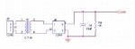
I m reading current of 0-0.5 ampere from current transformer the construction of a current transformer is such that it sense current at primary side & give AC voltage 0-5 VAC at secondary side & i connect a bridge rectifier to convert it in DC volt. The problem is the DC voltage does not match in every circuit therefore i need to add a variable resistor.

The circuit is attached kindly help me out how will i add the potentiometer in the same circuit, to maintain the same voltage against the ampere at the primary side.

What should be the value of variable rsistor.

Will my problem solve after adding variable resistor, let suppose my maximum current is 0.3 ampere i need to built 100 circuits after adding variable resistor i tune at DC side 3 VDC at 0.3 ampere at primary side, if my current consumption decreases to 0.1 ampere do the ratio of voltage drop will same in all 100 circuits i built or not.
 

Attachments

  • untitled.JPG
    untitled.JPG
    14.9 KB · Views: 74

If you want any accuracy the voltage drops across the recitfier diodes will be a problem. The diode drops will be nonlinear and vary greatly with temperature. I would place the load resistor (fixed + small variable in series) directly on the secondary of the transformer. Then I would use an op-amp rectifier if you want to get DC out. Maybe you can use the A/D to read the AC if you give it an offset and sync to the AC power cycle? You could use a op-amp inverter and use 2 A/D channels to read positive and negative peaks? There are RMS converter chips if that is what you want to read.

If your rectifier is linear the output should be linear to maybe 1%. To get better you need to be careful about the transformer and maybe use a flux balanced (or zero net flux) design with two secondaries, one for force and one for sense.
 

Hi,
The Current Transformer (CT) as you said has the fixed transfer ratio, until the ratio is not changed it will read the same voltage on secondary side with same current on primary side. And it depends all on your sensed voltage amplifier how you manage it. Just adding the variable resistor on the secondary side will nit give you a good accuracy. Better is you make a plugin type current sensing circuit (as a universal type for your circuits). The CT+voltage amplifier+signal conditioning for a good accuracy and trouble free measuring.
Here is just an exemplary circuit for your reference.
CT.jpg
 

I appreciate your work kindly let me know where will i place the variable resistor in the circuit i built also where should i connect the wiper pin of variable.

I just want to calibrate the current transformer i m using with this variable.

---------- Post added at 06:58 ---------- Previous post was at 06:06 ----------

Should i replace the resistor R9 by variable resistor.
 

Put the variable resistor in series with R9, and put them both across the transformer secondary. Connect the wiper to one end of the variable resistor.

Note if you put the variable resistor in parallel with R9, and you accidentally adjust it to near zero you may burn the variable resistor. The series connection prevents this.
 

HI,
Here is a practical circuit which I am using on all my UPS designs. I am posting it here for your reference if you can modify it according to your need.

Overload.jpg

Good Luck.
 

Hi RAZA,
Do you manage delay time for initial current(surge load) in your overload protection circuit.
Regards,
 

Status
Not open for further replies.

Part and Inventory Search

Welcome to EDABoard.com

Sponsor

Back
Top