Continue to Site

Welcome to EDAboard.com

Welcome to our site! EDAboard.com is an international Electronics Discussion Forum focused on EDA software, circuits, schematics, books, theory, papers, asic, pld, 8051, DSP, Network, RF, Analog Design, PCB, Service Manuals... and a whole lot more! To participate you need to register. Registration is free. Click here to register now.

using two ground points in circuit maker or another pSPICE tool

Status
Not open for further replies.

shreyas_patel21

Full Member level 3
Joined
Jan 4, 2011
Messages
181
Helped
15
Reputation
30
Reaction score
14
Trophy points
1,298
Activity points
2,325
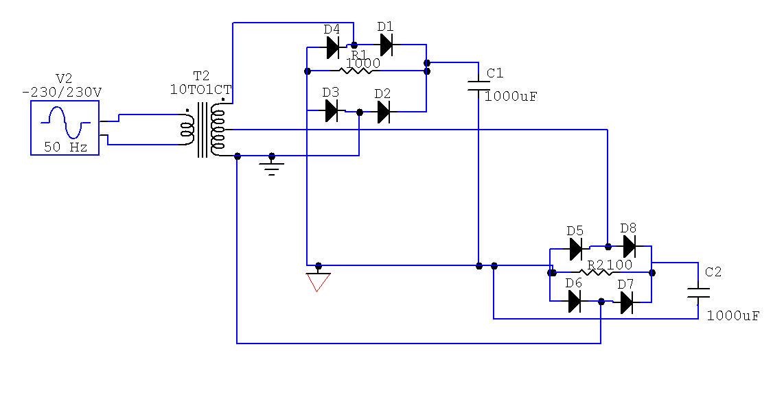
i am using circuit maker to simulate a my design which contains two rectifiers at secondary of dual tap transformer.

i have different grounds for ac and dc at rectifier in design,

how to put two different grounds in circuit maker?
 

I am not sure what your problem is. Maybe showing your circuit would help. Provided the primary and secondary are isolated then there shouldn't be a problem having a ground on both sides.

Keith
 

here is my schematic
how to give different grounds for ac and dc as shown in fig in circuit maker?


red color ground is DC ground
 
Last edited:

Connect a high value resistance (~ 100Meg) between two grounds.
 

Simply omit the AC ground symbol. There can't be two ground nodes with different potential.

If you want to measure voltages referred to the the "AC ground", use a differential measurement.
 

if you do not connect AC side ground, you may get floating node error in most of simulator. Some simulator automatically connect a high value resistance to avoid such error.
 

thank you all for suggestions..

I checked the DC output by putting ground at dc and checked ac by putting ground at ac
 

Status
Not open for further replies.

Part and Inventory Search

Welcome to EDABoard.com

Sponsor

Back
Top