Continue to Site

Welcome to EDAboard.com

Welcome to our site! EDAboard.com is an international Electronics Discussion Forum focused on EDA software, circuits, schematics, books, theory, papers, asic, pld, 8051, DSP, Network, RF, Analog Design, PCB, Service Manuals... and a whole lot more! To participate you need to register. Registration is free. Click here to register now.

Using timer in PIC18F

Status
Not open for further replies.

engr_joni_ee

Advanced Member level 3
Joined
Nov 3, 2018
Messages
750
Helped
2
Reputation
4
Reaction score
4
Trophy points
18
Activity points
6,226
Hi,

I am working on a program which has the following task to do every second

Turn ON pin B1 as output and wait for 100 ms
Read another pin B2 as input
Send a string to UART

Turn OFF the pin B1
Read again B2
Send a string to UART

Wait until the next second is over and then start again the process

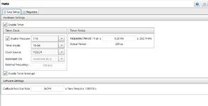
Can I use timer in this case ? i.e., just hold the program until the next second using timer and then start the process again
 

hello,

yes you can ..
use a timer in free mode, without interrupt.
it will do the job ..
just chek if time is elapsed at the end of main loop


Code:
Init Timer0;  // no interrupt needed
while(1)
{

reload TMR0
TMROIF=0;

Turn ON pin B1 as output and wait for 100 ms
Read another pin B2 as input
Send a string to UART

Turn OFF the pin B1
Read again B2
Send a string to UART

//wait elapsed time of 1 sec
while(TMROIF==0);
}
 

Hi,

yes, this is a suitable way to go.


****

alternative solutions are:
if you don´t have anything else to do:
* going to sleep instead of busy wait (to safe energy, for a battery operated device), configure timer to generate a wakeup.

or if you have to do some other tasks:
* configure the timer for 100ms. on_timeout: increment a counter every timeout: 0...9 and do:
.. when 0: Turn ON pin B1 as output
.. when 1: Read another pin B2 as input, Send a string to UART
.. when x: do whatever you want to be processed at this step

on no_timeout: do the other tasks
****************

so there is plenty of processing power (98%?) to do other tasks.

Klaus
 

Hi,

I am using MCC and have configured timer 0. I am not sure about the call back function rate. I am using 16 MHz internal oscillator. I have attached the generated files. The following functions are easy to understand.

void TMR0_Initialize(void)
void TMR0_StartTimer(void)
void TMR0_StopTimer(void)
void TMR0_Reload(void)

But I am not sure which function will check the interrupt "while(TMROIF==0)"
 

Attachments

  • Untitled 06.png
    Untitled 06.png
    26.3 KB · Views: 139
  • Untitled 07.png
    Untitled 07.png
    29.3 KB · Views: 147

Hi,

I guess the MCC comes with a manual. Did you read it?

But I am not sure which function will check the interrupt "while(TMROIF==0)"
I guess none of them. They all are for "controlling" TMR0.

And I guess you did no internet search.
I simple search brought me to this:
..step by step explained in detail.

and there will be many other sources of information.
even a youtube search for "PIC mcc timer0" gives numerous hits.

Klaus
 

My personal approach would be to set up a timer with interrupts every 10mS. In the ISR, count down as many variables as you like until they reach zero:
if(variable > 0) variable--;

Then to create a 1 second delay you load the variable with 100 (1S = 10mS * 100) and check it in your program loop to see if it is zero or not. For the 100mS delay, load another variable with 10 and again check if it has counted down to zero.
Doing it that way allows you to run several independent timers that can be loaded, with any delay you like, at any start time you like and operate almost in unison.

Brian.
 

Hi, I have enabled the following interrupts but not able to get the timer working.

Code:
    // Initialize the device
    SYSTEM_Initialize();
    TMR0_Initialize();

    // Enable the Global Interrupts
       INTERRUPT_GlobalInterruptEnable();

    // Enable the Peripheral Interrupts
       INTERRUPT_PeripheralInterruptEnable();

Inside the main function I am using these function under the while loop but it did not work.

Code:
 while (1)
    {
        // Add your application code
     
        TMR0_Reload();
        TMR0_StartTimer();

////////////////////////////////////////////////
// Perform the task
////////////////////////////////////////////////            
     
   // wait elapsed time of 1 sec
      TMR0_ISR();
      TMR0_StopTimer();  
    }

I have attached tmr0.c where all the functions are defined.


Code:
#include <xc.h>
#include "tmr0.h"

/**
  Section: Global Variables Definitions
*/

void (*TMR0_InterruptHandler)(void);

volatile uint16_t timer0ReloadVal;

/**
  Section: TMR0 APIs
*/


void TMR0_Initialize(void)
{
    // Set TMR0 to the options selected in the User Interface

    //Enable 16bit timer mode before assigning value to TMR0H
    T0CONbits.T08BIT = 0;

    // TMR0H 255;
    TMR0H = 0xFF;

    // TMR0L 55;
    TMR0L = 0x37;

    
    // Load TMR0 value to the 16-bit reload variable
    timer0ReloadVal = (uint16_t)((TMR0H << 8) | TMR0L);

    // Clear Interrupt flag before enabling the interrupt
    INTCONbits.TMR0IF = 0;

    // Enabling TMR0 interrupt.
    INTCONbits.TMR0IE = 1;

    // Set Default Interrupt Handler
    TMR0_SetInterruptHandler(TMR0_DefaultInterruptHandler);

    // T0PS 1:2; T08BIT 16-bit; T0SE Increment_hi_lo; T0CS FOSC/4; TMR0ON enabled; PSA assigned;
    T0CON = 0x90;
}

void TMR0_StartTimer(void)
{
    // Start the Timer by writing to TMR0ON bit
    T0CONbits.TMR0ON = 1;
}

void TMR0_StopTimer(void)
{
    // Stop the Timer by writing to TMR0ON bit
    T0CONbits.TMR0ON = 0;
}

uint16_t TMR0_ReadTimer(void)
{
    uint16_t readVal;
    uint8_t readValLow;
    uint8_t readValHigh;

    readValLow  = TMR0L;
    readValHigh = TMR0H;
    readVal  = ((uint16_t)readValHigh << 8) + readValLow;

    return readVal;
}

void TMR0_WriteTimer(uint16_t timerVal)
{
    // Write to the Timer0 register
    TMR0H = timerVal >> 8;
    TMR0L = (uint8_t) timerVal;
}

void TMR0_Reload(void)
{
    // Write to the Timer0 register
    TMR0H = timer0ReloadVal >> 8;
    TMR0L = (uint8_t) timer0ReloadVal;
}

void TMR0_ISR(void)
{
    static volatile uint16_t CountCallBack = 0;

    // clear the TMR0 interrupt flag
    INTCONbits.TMR0IF = 0;

    // reload TMR0
    // Write to the Timer0 register
    TMR0H = timer0ReloadVal >> 8;
    TMR0L = (uint8_t) timer0ReloadVal;

    // callback function - called every 10000th pass
    if (++CountCallBack >= TMR0_INTERRUPT_TICKER_FACTOR)
    {
        // ticker function call
        TMR0_CallBack();

        // reset ticker counter
        CountCallBack = 0;
    }

    // add your TMR0 interrupt custom code
}

void TMR0_CallBack(void)
{
    // Add your custom callback code here

    if(TMR0_InterruptHandler)
    {
        TMR0_InterruptHandler();
    }
}

void TMR0_SetInterruptHandler(void (* InterruptHandler)(void)){
    TMR0_InterruptHandler = InterruptHandler;
}

void TMR0_DefaultInterruptHandler(void){
    // add your TMR0 interrupt custom code
    // or set custom function using TMR0_SetInterruptHandler()
}
 

Hi,

You don´t understand how it works.

May I ask which tutorials you´ve read which videos you watched ... to get to this conclusion?
Please provide links to them, so we can discuss about it. Step by step.

Klaus
 

Hi,
I have read about the timer chapter. There is a timer clock which is FOSC/4 that gives 4 MHz because I am running the internal Oscillator with 16 MHz.

The time period will be then 1/4MHz = 0.25 us

In order to make it 1 s, I need to load 16 bit register TMR0L and TMR0H. These registers increment and when they reach 0xFFFF, there is a timer interrupt that need to be clear and the timer need to be stared again by loading new starting values to the registers TMR0L and TMR0H.

If I load the registers TMR0L and TMR0H with 0x0000 then the timer interrupt will appear after 65535 x 0.25 us = 16384 us which is 16.384 ms and can not reach 1 s which I need.

Here I have two questions, one the correct value of these two registers TMR0L and TMR0H and the second question is that if I am calling the functions at the right sequence ?
 

While post#9 is correct it still does not fit to your code.
The code of post#7 uses a C library, while your explanation is raw silicon behaviour.

Decide whether you want to use C library or not. Yes or no. Then focus on your decision, read the regarding document, give us the link. Don´t mix.

Klaus
 

Also which 'PIC18F' are you using (please be exact).
Typically the TMR0 of that family of MCUs has the most limitations but there are devices in that family that have other timers that may well be better for your needs.
Also you seem to be trying to use MCC - you either need to read up on how MCC works, especially in regard to the timer callbacks, OR you need to write your own code (without MCC) that handles the timer and especially interrupt. Timers are very straight forward modules and MCC can complicate things (as it tries to mask the differences across a very large number of devices in different families).
Either way, if you have a function with 'ISR' in the name, the chances are that you should NEVER call that yourself. If you think you need to then you have not understood how ISRs work.
Susan
 

I see that this function "TMR0_ISR()" actually clears the interrupt and then reloads the TMR0.

Which function should I use that wait until the interrupt occur ? Is that "TMR0_CallBack()" function that will hold and wait until the interrupt occur ? If yes then I should call "TMR0_ISR()" which is the interrupt service routine.
 

Hi,

That´s the key benefit of the interrupt: You don´t need a function to wait for it to come.

--> Read most basic tutorials about interrupts.

Klaus
 

Yes, I don't need to write own function that wait for interrupt. My question is what should I write in the code that check the interrupt and hold there until the interrupt appear. Can this be done by "while(TMROIF==0);" or "TMR0_CallBack()" function from the "tmr0.c" can do this task ?
 

Hi,

The benefit of the interrupt is that you usually don`t need to care about it.
The interrupt is triggered automatically and the callback function is executed automatically.

So please tell us why you think you need to wait for it .. or check for it?

* TMR0IF does not work.
* TMR0_CallBack is executed automatically. (you don´t need to call it)

Klaus
 

If "TMR0_CallBack()" execute automatically then I guess I don't need to add in the main.c file but when it activate, would it also call "TMR0_ISR()" as well. I don't see it calling in the body of "TMR0_CallBack()".

On the other hand, the function "TMR0_ISR()" that clears the interrupt, reloads the TMR0 and also calls "TMR0_CallBack()". Do I need to add this function in the while loop in the main.c

I understand the the reloading values in the register TMR0L and TMR0H are not giving 1 sec but I will calculate them latter. My first concern is to make the code working with any reloading values in TMR0L and TMR0H.


Code:
 while (1)
    {
        // Add your application code
    
        TMR0_Initialize(); 
        TMR0_StartTimer();

////////////////////////////////////////////////
// Perform the task
////////////////////////////////////////////////           
    
   // wait elapsed time of 1 sec
      TMR0_ISR();
      TMR0_StopTimer(); 
    }
 

Hi,

Eventually read some documents???

read the code you posted in post#7:

The interrupt executes the TMR0_ISR(). (every related C tutorial, every library tutorial will tell you this)
...within the TMR0_ISR the counter is handled an on match/overflow the TMR0_CallBack is executed.

Before you ask: No, the TMR0_ISR does not need to be executed manually. It is called automatically.

****
I'm getting impatient, because I don´t see you to follow the recommendations to read/view some tutorials. And give the links to them.
Also you don´t explain what you want to achieve.
A forum can´t replace school, it can´t repalce reading/viewing tutorials.

Klaus
 

Hi,

I have read the tutorial mentioned in post # 5

This tutorial explains how to use timer interrupt to perform a task after a particular delay. We need to enable the global interrupt and peripheral interrupt inside the main (). Whenever the interrupt comes it will call the function "TMR0_ISR()", there is no need to add any code that calls "TMR0_ISR()" because this function will be called automatically whenever the timer over flow happen signaled by the timer interrupt. Inside this function "TMR0_ISR()" we should have our task that need to be done upon the timer interrupt.

I also read the tutorial on how to use timer polling.


Here I know that we don't need to enable timer interrupt in polling example because it is based on polling which means that we need to check the timer and again at some point in our code until the over flow happen and when the timer over flow happen, we need to reload the timer registers and start the timer again in the while loop.

Code:
 while (1)
    {
        // Add your application code
        if (TMR0_HasOverflowOccured()) //Has Timer0 Overflowed?
        {
            IO_RA2_Toggle(); //Switch state of RA2 LED when overflow occurs
            TMR0IF = 0;      //Clear the Timer0 overflow flag
        }
    }

I think I need to use timer polling in my task because I need to wait inside the while loop until the next second is over and that can only be done by implementing the timer polling example. I have described my task in the first post. Kindly comment here if I am thinking right or not.
 

No. You do not have to poll the timer.
When the timer rolls over from maximum to zero, assuming interrupts are enabled, it AUTOMATICALLY calls the ISR. It is done in the silicon, not by your program. When the interrupt occurs, the critical registers for recovery are saved, including the program counter so it can resume from its state before the interrupt, then the address of the ISR (0x0008) is loaded into the program counter so it starts running the code from there. For code that completes in a very short time you can run it in the ISR itself but a better strategy is usually to set a 'flag' (a bit or variable used as an indicator) inside the ISR then to exit it so your program resumes. The main program will continue where it left off, it will not be aware the interrupt ever occurred except that the flag will be set.

If you follow the idea in post #6 you can run multiple timers simultaneously, each with different periods and they can be started, stopped and overlap without interacting. You can generate all the delays you need with one simple ISR and a flag for each delay you create.

Brian.
 

I also read the tutorial on how to use timer polling.


Here I know that we don't need to enable timer interrupt in polling example because it is based on polling which means that we need to check the timer and again at some point in our code until the over flow happen and when the timer over flow happen, we need to reload the timer registers and start the timer again in the while loop.

Code:
 while (1)
    {
        // Add your application code
        if (TMR0_HasOverflowOccured()) //Has Timer0 Overflowed?
        {
            IO_RA2_Toggle(); //Switch state of RA2 LED when overflow occurs
            TMR0IF = 0;      //Clear the Timer0 overflow flag
        }
    }

I think I need to use timer polling in my task because I need to wait inside the while loop until the next second is over and that can only be done by implementing the timer polling example. I have described my task in the first post. Kindly comment here if I am thinking right or not.

i agree with you, it was my proposal in post#2
your application is simple and (maybe) don't need use of interrupt .. to get a loop time of 1 sec
but depends of your MCU Type ? and FOSC value ?
old 16F MCU with 8bits TMR0 could not reah 1sec elapsed time
in this case you must use interrupt to count accumulate elementary times ie =100mS * 10 times => 1sec
and it is a good way to increase your knowlege about PIC
 

Status
Not open for further replies.

Similar threads

Part and Inventory Search

Welcome to EDABoard.com

Sponsor

Back
Top