Continue to Site

Welcome to EDAboard.com

Welcome to our site! EDAboard.com is an international Electronics Discussion Forum focused on EDA software, circuits, schematics, books, theory, papers, asic, pld, 8051, DSP, Network, RF, Analog Design, PCB, Service Manuals... and a whole lot more! To participate you need to register. Registration is free. Click here to register now.

Using step down transfomer for inverter project

Status
Not open for further replies.

treemon

Member level 3
Joined
Nov 2, 2022
Messages
60
Helped
0
Reputation
0
Reaction score
4
Trophy points
8
Activity points
402
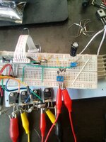
I am working on a 12v, EGS002 based sine wave inverter, right now I dont have a proper step-up transformer so I used a regular step down 220 vac to 12vac transformer.. Its rated > 500w

After facing voltage drop issue even with small 9w load connected to AC side. Learning from others experience, I understood this transformer setup wont work on a 12v dc supply.

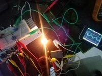
So just for testing idea, I raised the input DC supply voltage to about 17v and now I get 50hz/12VAC on primary side of transformer, tested using a voltmeter (and also oscilloscope) at no load

Still voltage drop happens just like before. My question is ? Do I need to replace transformer?

I have connected ac side feedback
 
Last edited:

Are you using sufficient inductance in series with the primary? (ie the "primary" that the vendor meant to be the secondary)
Is you primary current looking sinusoidal?
 

Are you using sufficient inductance in series with the primary? (ie the "primary" that the vendor meant to be the secondary)
Is you primary current looking sinusoidal?

Yes I have connected LC filter before input goes into primary, else waveform were not sinusoidal.
I have checked using mini oscilloscope input is just fine.

Later I removed the transformer part to attach some load directly on that output of H-bridge -> LC filter,
it appears voltage is being fixed at 8.4 vrms (for 12 vdc @ no load ) no matter how much i adjust VFB..
I do not understand.

Although the undervoltage & overvoltage lockout is functioning so I cant say voltage feedback is faulty.
If this EGS002 board cannot adjust spwm duty cycle in this simple scenario how would it work with transformer !!!


Today I will test more...

16759853787922603415301807213379.jpg
 
Last edited:

The primary consists of many turns of thin wire. Normal usage has a power transformer designed to offer high impedance to the electric company.
Raw math calculates as 97 ohms when drawing 500 Watts at 220 VAC.
970 ohms when drawing 50W.

So when operating it in reverse direction, you're driving a new load from an unknown impedance inside the transformer. We should expect meager current flow when a load is in place of the electric company .

xfmr primary hi imped to electric company.gif
 

The primary consists of many turns of thin wire. Normal usage has a power transformer designed to offer high impedance to the electric company.
Raw math calculates as 97 ohms when drawing 500 Watts at 220 VAC.
970 ohms when drawing 50W.

So when operating it in reverse direction, you're driving a new load from an unknown impedance inside the transformer. We should expect meager current flow when a load is in place of the electric company .

View attachment 181122

You mean unknown impedance of secondary side? I didn't understand from your second paragraph, is this approach not doable? I am only testing my circuit with littlle load... I will arrange a proper transformer if successful.
 

Hi,

12V / sqrt(2) = 8.48 V
What output voltage do you expect?

Klaus
This is where I am unclear, also my second post was little confusing to you. Well I know, ideally it should keep it at 8.4v, but whats then voltage feedback pin for?

Now i have connected VFB to a trumpet voltage divider and not AC source, I am manually adjusting what goes in driver board

If voltage drops it should be able to give more than 8.4v at no load, assuming the duty cycle is increased. I am not clear.
 

Would be really helpful to see a sketch of the setup, e.g. how you connected the feedback.

I used usual AC rectified feedback with 2x 100k resistance in parallel to a 10k potentiometer. But now i have removed transformer and feedback is conneted to a 10k voltage divider for manual adjustment, voltage regulation should work without transformer also right?

I mean i should be able to regulate 8.4 vac coming from h bridge.
 

Attachments

  • Screenshot_2023-02-10-12-27-57-036.jpeg
    Screenshot_2023-02-10-12-27-57-036.jpeg
    224.6 KB · Views: 83

Hi,
, but whats then voltage feedback pin for?
Obviously it can't regulate more than 8.4V, thus it just can regulate downwards.
Maybe 6V...8.4V.
--> thus use a transformer with a higher voltage ratio.

Klaus

You used a 220V --> 12V transformer.
Now the "12V" is at nominal load. To compensate for the voltage drop caused by the load current the transformer was designed for a higher output voltage at no load. Maybe 13.5V (winding ratio 220 : 13.5)
Now if you connect this transformer to 12V RMS (which is impossible in your configuration)..
It would output 195V on no load, and even less when load is applied.
With 8.4V RMS input you could expect 137V @ no load. Les with load.(example values)

Klaus
 
Last edited:
Hi,

Obviously it can't regulate more than 8.4V, thus it just can regulate downwards.
Maybe 6V...8.4V.
--> thus use a transformer with a higher voltage ratio.

Klaus

You used a 220V --> 12V transformer.
Now the "12V" is at nominal load. To compensate for the voltage drop caused by the load current the transformer was designed for a higher output voltage at no load. Maybe 13.5V (winding ratio 220 : 13.5)
Now if you connect this transformer to 12V RMS (which is impossible in your configuration)..
It would output 195V on no load, and even less when load is applied.
With 8.4V RMS input you could expect 137V @ no load. Les with load.(example values)

Klaus
Upper limit of 8.4 and regulation below sound logical, however in reality it doesn't do any downward regulation, i checked. It simply stops when VFB cross a threshold on either side, in between voltage stays flat 8.4v

I have eliminated transformer part for simplication. I connect a 12v filament type bulb from automobile at 8.4 vac output, also connected voltage feedback as usual. Still no regulation. Bulb glows and voltage drops and driver is shut.

I am using 4x FGA25N120 IGBT in bridge... In all manual and connected VFB doesnt work, waveform also gets easly distorted with small load.
 
Last edited:

Hi,

if you remove the transformer ... how can the feedback be "as usual"?
Makes no sense to me.

What is the expected V_FB?
And what is the measured/tested V_FB range?

Klaus
 

Hi,

if you remove the transformer ... how can the feedback be "as usual"?
Makes no sense to me.

What is the expected V_FB?
And what is the measured/tested V_FB range?

Klaus
Feedback i now take from LC filter output, which earlier went into transformer. I changed resistance from 2x100k ohm to 1x10kohm in series. VFB is now maintained about 3v and board works fine as long as no load connected
Expected VFB is 2.75 to 3.1v
 

Attachments

  • 16760274291696691027927034526980.jpg
    16760274291696691027927034526980.jpg
    2.5 MB · Views: 83

Hi,

I don´t hink this is correct:
--> I expect a "fixed" voltage for V_FB not a range of 2.75V ... 3.1V

* No information about the measured/tested voltage range.

* No schematic/draft about the FB wiring.

Now post#14 ... I´m about to leave.

Klaus
 

Hi,

I don´t hink this is correct:
--> I expect a "fixed" voltage for V_FB not a range of 2.75V ... 3.1V

* No information about the measured/tested voltage range.

* No schematic/draft about the FB wiring.

Now post#14 ... I´m about to leave.

Klaus
Ok, now some improvements :) driver did not turn off with load. My mistake was I used a big capacitor for VFB which charged very slow and undervoltage timeout was kicked in before that... I had to connect voltmeter permanently on VFB to find out this issue

Still after load waveform is distorted.....
 

Attachments

  • 16760324224336872820249916919565.jpg
    16760324224336872820249916919565.jpg
    2.3 MB · Views: 72

Status
Not open for further replies.

Similar threads

Part and Inventory Search

Welcome to EDABoard.com

Sponsor

Back
Top