Continue to Site

Welcome to EDAboard.com

Welcome to our site! EDAboard.com is an international Electronics Discussion Forum focused on EDA software, circuits, schematics, books, theory, papers, asic, pld, 8051, DSP, Network, RF, Analog Design, PCB, Service Manuals... and a whole lot more! To participate you need to register. Registration is free. Click here to register now.

Using RF signal generator as tracking generator

Status
Not open for further replies.

Palpurul

Member level 3
Joined
May 31, 2016
Messages
66
Helped
9
Reputation
18
Reaction score
8
Trophy points
8
Location
Turkey
Activity points
593
Is it possible to use a RF signal generator as tracking generator along with a sprectrum analyzer? I've been reading many datasheets and discovered that the tracking generators that are integrated to the spectrum analyzers don't very good amplitude accuracy. To get more accurate measurements I thought maybe RF gen can be used. I know you can normalize and calibrate this out, but when measuring amplifiers +-3dB in the input power could still be a problem if the DUT has low dynamic range. Is it possible? If it's possible what do I need in a spectrum analyzer and RF gen?
 

I don't see why its going to be a problem if you remove your amplifier, then normalize through your entire test set up, including any cables, attenuators, or whatever else there is.

Get the gain dead flat through the self calibrating normalization process.

Insert your amplifier... and there it is.

Let me tell what my worry is. Let's assume that I what to see how my amplifier performs with input power +20dBm and I set tracking generator to +20dBm. The problem is the tracking gen has +-3dB accuracy in amplitude and if my amplifier does not operate in the linear region with power around +23dbm the accuracy of the tracking gen is going to be a problem even if I do normalize the spectrum analyzer before I take the measurement.
 

Your tracking generator when normalized should be more like +/- 0.1 db over any reasonable bandwidth.
That's the whole idea of it.
It very slowly sweeps and automatically corrects the output level, which generates some kind of gain correction lookup table which it then applies during normal use.

I suggest you study the operators manual for your particular spectrum analyser.
Something with +/- 3db normalized gain flatness is so unbelievably bad It must be faulty.

WOW really nice suggestion. I always thought the normalization proccess is purely done in software. You are actually saying that there is some kind of electronic correction involved in normalization. However, I've never seen amplitude accuracy after normalization specified in a datasheet. Better start to look for it.
 

WOW really nice suggestion. I always thought the normalization proccess is purely done in software. You are actually saying that there is some kind of electronic correction involved in normalization. However, I've never seen amplitude accuracy after normalization specified in a datasheet. Better start to look for it.

There would be no point in doing it in software if the real RF levels are all over the place.

At least in my own spectrum analyser there is a variable gain stage in the tracking generator, as well as the switched gain attenuator right at the tracking generator output. The variable gain stage is driven from a DAC that is hooked up to a lookup table. So it slowly sweeps and carries out multiple gain corrections at a great many points over the entire bandwidth of the instrument. Its the only way it could possibly work from a few Khz through to several Ghz.

Its the tracking generator that is usually the problem, the wideband power amplifier can never be completely flat. The receiver front end part is just a mixer and should be (and is) much flatter.

Maybe other spectrum analysers work differently ?
Best to check the book of words, and see what it says.

I beleive only way to learn this is to e-mail the manufacturer because I've never seen such a thing in a datasheet, and also the accuracy after normalization is not specified as well. It's kind of disturbing to not know the uncertainty.

Returning to my first question. Is it possible to use RF generator as track gen? Do you know anything about this?
 

So how do you get an external RF generator to track the spectrum analyser ?

You can easily see the accuracy after normalization.
Set the vertical scale to 1db per division and sweep the entire band.
 

If you refer to absolute tracking generator level as discussed in post #1 and #3, +/- 2dB to +/- 3dB seems to be a realistic output flatness specification plus an absolute level error of e.g. 0.5 to 1 dB. Relative level error can be easily reduced in a through calibration.

Either if tracking generator absolute level accuracy is a common problem or not, the considerations are so far plausible.

If you can utilize a probably more accurate signal generator for your measurements is more a problem of particular instrument features rather than a useful general question. If you want to perform a sweeped measurement, your generator must have a sweep feature. Does it? To perform a synchronized analyzer sweep, generator and SA need trigger-out/trigger-in options and a precise frequency sweep definition.

But at the discussed high signal level, the SA must not necessarily be synced. It can perform a fast asynchronous wideband scan with peek hold to acquire the gain curve. You can even tune the generator frequency manually.
 

While I have often used the tracking generator as a handy carrier source, with sweep width set to zero. I cannot really see any advantages of using an external synthesized RF generator, if you already have a built in tracking generator.
Its going to need to track fairly well, or you are going to slide down the sides of the bandpass filter and lose amplitude without any real way of knowing that is happening.

At least on my spectrum analyser I can get a dead straight horizontal line after normalisation. I know for a fact it has the variable gain amplifier in the tracking generator.
Thinking about it, there may also be some software fine tuning of gain as well, in addition to the analog amplitude levelling.

While the schematic tells the hardware side of things plainly enough, the software side is a bit more mysterious.
 
While I have often used the tracking generator as a handy carrier source, with sweep width set to zero. I cannot really see any advantages of using an external synthesized RF generator, if you already have a built in tracking generator.

At least on my spectrum analyser I can get a dead straight horizontal line after normalisation. I know for a fact it has the variable gain amplifier in the tracking generator.
Thinking about it, there may also be some software fine tuning of gain as well, in addition to the analog amplitude levelling.

While the schematic tells the hardware side of things plainly enough, the software side is a bit more mysterious.

Can you tell me what spectrum analyzer you are using?
Its going to need to track fairly well, or you are going to slide down the sides of the bandpass filter and lose amplitude without any real way of knowing that is happening..

That's a really good point.
 
Last edited:

Its an ancient Advantest R3361A 9Khz to 2.6 Ghz.
Its just for home hobby use, but works amazingly well for what it is.
 

Well I read many datasheets and application notes. I have found nothing indicating that the normalization process actually "fine tunes" the output power of the tracking gen in hardware. I beleive normalization is done mosly in software. Morever, in the datasheets there is no information provided about the amplitude accuracy of the output of the tracking generator after normalization.
 

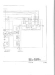
Just looking at the schematics in my service manual right now.

There is a block diagram of the tracking generator with an ALC input going to something they call a pin modulator.
This is carried out before mixing down to the final tracking generator output frequency, and before the tracking generator power amplifier and output switched attenuator.

That would make sense, because any harmonics created by clipping the amplitude would be eliminated in the low pass filter after the mixer.

tracking gen.jpeg
 
Just looking at the schematics in my service manual right now.

There is a block diagram of the tracking generator with an ALC input going to something they call a pin modulator.
This is carried out before mixing down to the final tracking generator output frequency, and before the tracking generator power amplifier and output switched attenuator.

That would make sense, because any harmonics created by clipping the amplitude would be eliminated in the low pass filter after the mixer.

View attachment 135250

Some nice old schematic right here:D. Thanks for sharing that.
 

Yes its a bit of a fossil by modern day standards, but these things cost $75K new without any options thirty years ago.
Serious money back then.
Still works great, the self calibration is magic, and for only a few hundred dollars on e-bay.
 

Status
Not open for further replies.

Part and Inventory Search

Welcome to EDABoard.com

Sponsor

Back
Top