arnab913
Junior Member level 3
- Joined
- Jul 27, 2012
- Messages
- 30
- Helped
- 0
- Reputation
- 0
- Reaction score
- 0
- Trophy points
- 1,286
- Location
- Chittagong, Bangladesh
- Activity points
- 1,515
Hello,
I am working with the 16f877A,using PWM with ADC. I've writtten a code,but it is not working.....I am cheaking it again & again..but nothing. :-(
The motor works without the ADC value...wheather it is 5 or 0V.
I don't understand why???
Here is the code....
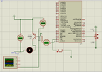
Oscilloscope is not also showing PWM! Pls help.....
Here the image

I am working with the 16f877A,using PWM with ADC. I've writtten a code,but it is not working.....I am cheaking it again & again..but nothing. :-(
The motor works without the ADC value...wheather it is 5 or 0V.
I don't understand why???
Here is the code....
Code:
double pwm;
void main() {
   PWM1_Init(1000);              // PWM of 1kHz
  ADCON1=101000010;
  TRISA=0b00000001;
  PORTA=0;
   TRISB=0b00000010;             // portb as output
   PORTB=0;
   PWM1_Start();         // starting PWM
   if (PORTB.f1==1)
    {
 while(1)
  {

    pwm=ADC_Read(0);
   PWM1_Set_Duty(pwm);

            }
   delay_ms(100);
     }
}Here the image
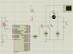
")