Welcome to our site! EDAboard.com is an international Electronics Discussion Forum focused on EDA software, circuits, schematics, books, theory, papers, asic, pld, 8051, DSP, Network, RF, Analog Design, PCB, Service Manuals... and a whole lot more! To participate you need to register. Registration is free. Click here to register now.
as tittle above, how do i do connection for the drive the mos switch by hpcl-3120. like which pin to the Gate of mos and drains, and what should i connect to the anode and cathode pins of the opto driver
as tittle above, how do i do connection for the drive the mos switch by hpcl-3120. like which pin to the Gate of mos and drains, and what should i connect to the anode and cathode pins of the opto driver
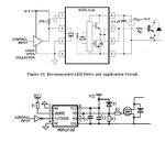
If you are intending to drive a nMOS for a high side switch, you may want to try the configuration as attached. That is the design I've made for using a 3120 optocoupler to drive a nMOS high side switching using bootstrap technique learned from here: (https://www.fairchildsemi.com/an/AN/AN-6076.pdf)
The resistor must be placed in series with the photodiode to limit the current to the OEM's specified ampere range. It's value could be pre-determined by using the input voltage minus away the turn on voltage (forward voltage drop of the photodiode when conducting) and then divide by the current "permissable". That is, using V=IR, hence R=V/I = (Vin-Vf)/I = (Vin-1.5)/0.01
For example, if your Vin = 5V, then your R would be 350 ohms. Now you can try sub back R = 350 ohms into I=V/R equation and you'll see that even for whatsoever reason the Vf goes above its typical value to its max. value = 1.8V (as specified in datasheet, your current = I=V/R = (5-1.8)/350= ~9.142mA and that is still well safe above the min. limit rated current (7mA) for the photodiode to conduct.
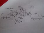
im using the optocoupler to drive the switches in 2 switches foward converter. for the cathode and anode , pin 2 and pin 3 in hpcl 3120 , is it we just connect to the function generator to supply the PWM into the hpcl 3120?
---------- Post added at 12:40 ---------- Previous post was at 12:38 ----------
If you are intending to drive a nMOS for a high side switch, you may want to try the configuration as attached. That is the design I've made for using a 3120 optocoupler to drive a nMOS high side switching using bootstrap technique learned from here: (https://www.fairchildsemi.com/an/AN/AN-6076.pdf)
The resistor must be placed in series with the photodiode to limit the current to the OEM's specified ampere range. It's value could be pre-determined by using the input voltage minus away the turn on voltage (forward voltage drop of the photodiode when conducting) and then divide by the current "permissable". That is, using V=IR, hence R=V/I = (Vin-Vf)/I = (Vin-1.5)/0.01
im using the optocoupler to drive the switches in 2 switches foward converter. for the cathode and anode , pin 2 and pin 3 in hpcl 3120 , is it we just connect to the function generator to supply the PWM into the hpcl 3120?
For example, if your Vin = 5V, then your R would be 350 ohms. Now you can try sub back R = 350 ohms into I=V/R equation and you'll see that even for whatsoever reason the Vf goes above its typical value to its max. value = 1.8V (as specified in datasheet, your current = I=V/R = (5-1.8)/350= ~9.142mA and that is still well safe above the min. limit rated current (7mA) for the photodiode to conduct.
im using the optocoupler to drive the switches in 2 switches foward converter. for the cathode and anode , pin 2 and pin 3 in hpcl 3120 , is it we just connect to the function generator to supply the PWM into the hpcl 3120?
im using the optocoupler to drive the switches in 2 switches foward converter. for the cathode and anode , pin 2 and pin 3 in hpcl 3120 , is it we just connect to the function generator to supply the PWM into the hpcl 3120?
---------- Post added at 12:40 ---------- Previous post was at 12:38 ----------
im using the optocoupler to drive the switches in 2 switches foward converter. for the cathode and anode , pin 2 and pin 3 in hpcl 3120 , is it we just connect to the function generator to supply the PWM into the hpcl 3120?
As mentioned previously, the resistor to-be connected in series with the photodiode (doesnt matter with pin 2 or 3 because it is a series connection) would limit the current (coming from the PWM generator) to a safe limit as instructed by the manufacturer seen in the datasheet. To calculate the value of the resistor, please see my previous post.
This site uses cookies to help personalise content, tailor your experience and to keep you logged in if you register.
By continuing to use this site, you are consenting to our use of cookies.