Welcome to our site! EDAboard.com is an international Electronics Discussion Forum focused on EDA software, circuits, schematics, books, theory, papers, asic, pld, 8051, DSP, Network, RF, Analog Design, PCB, Service Manuals... and a whole lot more! To participate you need to register. Registration is free. Click here to register now.
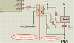
I designed a circuit to drive a load.i used two supply(Vcc=5).
Is the circuit that I have designed correct or not?
Is there any another design to drive a device else using relay(I don't want use Relay).
tnx
Your circuit may work but also may not. That's because the gate trigger current is too small to guarantee triggering. The Q4006L4 is not a very sensitive type and needs a substantial amount of gate current to ensure triggering - 25mA in QI-III and 50mA in QIV. Your circuit supplies only about 15mA (approx. 9mA via Q1 collector, 6mA from base. Total about 15mA through emitter). It may still work because the 25/50mA figures are for guaranteed triggering but we can't be certain it will trigger with 15mA. Lowering the value of Q1's collector resistor will help.
It's also a good idea to a resistor between the gate and T2 of the triac to bleed off any leakage current and prevent unwanted self-triggering.
An alternative is to use an optoisolator triac driver like one of the MOC30xxx series.
This site uses cookies to help personalise content, tailor your experience and to keep you logged in if you register.
By continuing to use this site, you are consenting to our use of cookies.