Continue to Site

Welcome to EDAboard.com

Welcome to our site! EDAboard.com is an international Electronics Discussion Forum focused on EDA software, circuits, schematics, books, theory, papers, asic, pld, 8051, DSP, Network, RF, Analog Design, PCB, Service Manuals... and a whole lot more! To participate you need to register. Registration is free. Click here to register now.

using FNA41560 for 3 phase inverter

Farazniaz

Newbie
Joined
Apr 26, 2023
Messages
4
Helped
0
Reputation
0
Reaction score
0
Trophy points
1
Activity points
45
Is anyone here have some knowledge about FAIRCHILD FNA41560 Smart Power Module ?
We are working on a project making a 3 phase inverter using fna41560 but we are having issues in getting results. We have used 3 phase PWM signal from arduino UNO (for testing) and did connections all according to the datasheet, in datasheet there is a application circuit diagram everything is done according to that diagram but still we are having troubles.

Resistors and Capacitors values are also according to the circuit (minor differences).

We have given 15V DC for Vcc for IC

For dc link we have given 20 V-35V dc (for testing).
 

Attachments

  • FNA41560_1010.PDF
    1.1 MB · Views: 84
Last edited:
Hi,


None does tell about the problem

--> Please give a clear error description, how you test it and what you expect.

Also post your schematic and your PCB layout.

Klaus
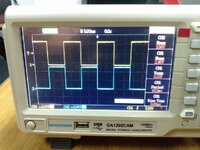
1682592458774.jpeg This is the input pwm for 1 phase.
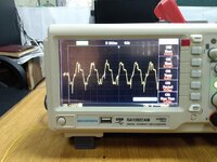
1682592414831.jpeg This is an output I am getting.
Neither I am getting a sinusoidal wave nor a proper rms value.
The page 3 in the file attached shows the schematic of the circuit.
The video attached shows the pcb of the circuit. The components are attached on a veroboard because I assume that I might have to change some components so on pcb it will be difficult to change the components from the pcb. I am giving 20-40V dc input but on the datasheet, it is wriiten in recommended parameters to give 400V. So, can it cause a problem?
 

Attachments

  • rd-344.pdf
    764.9 KB · Views: 116
  • WhatsApp Video 2023-04-27 at 15.57.29.mp4
    2.8 MB
O.K.

1) why do you expect a sinusoidal output? I can´t find "sinus..." is mentionend in the document at all.

2) we don´t see how and where the scope is connected.

3) what RMS value do you excpect?

4) do you agree that the schematic of page 3 is likely to work properly. Do you also agree that your circuit does not work properly. I clearly asked about "your schematic". How do you think we can find an issue in your circuit while you don´t show.

5) this is not a PCB layout at all. Just extended wires. You did not follow any of the PCB layout guidance recommendations.

**
Please follow the design rules. There is a good reason why they take the effort to
If you ned help, please provide useful informations.

You showed a mature datasheet as well as a mature design guide. Please go to onsemi.com to the modules´ site and read through the related documents. They explain everything in detail.

Klaus
 
You are sending 50 Hz square wave to the power module, how can you expect sine output? Instead you would send sine pwm with 10 to 20 kHz carrier frequency.
 
.. but then still you need some kind of filter.
The module itself will never output a sinewave.

Klaus
 
O.K.

1) why do you expect a sinusoidal output? I can´t find "sinus..." is mentionend in the document at all.

2) we don´t see how and where the scope is connected.

3) what RMS value do you excpect?

4) do you agree that the schematic of page 3 is likely to work properly. Do you also agree that your circuit does not work properly. I clearly asked about "your schematic". How do you think we can find an issue in your circuit while you don´t show.

5) this is not a PCB layout at all. Just extended wires. You did not follow any of the PCB layout guidance recommendations.

**
Please follow the design rules. There is a good reason why they take the effort to
If you ned help, please provide useful informations.

You showed a mature datasheet as well as a mature design guide. Please go to onsemi.com to the modules´ site and read through the related documents. They explain everything in detail.

Klaus
1) I suppose that it is an inverter ic so it will give sinusoidal wave. But the thing is that, the wave I am getting is not like any of the output waveforms of inverter.
2). The scope is connected between phase(U,V,W) pins and the negative dc link.
3). I am not expecting any rms value. The thing is that it is not changing whether I give it 15V dc or 40V dc.
4). The circuit on page 3 is likely to work properly because it is the application circuit given in its datasheet.
5). The circuit is on veroboard while the ic is on pcb. This is because we are now just testing it.

I am sure about it that the circuit is made correctly and there is no connection mistake.
I have to do this project within 2 weeks and first time I am making such a complex circuit. That's why I am so confused and post my question here on urgent basis.
I am new on edaboard that's why I don't have any idea that which things to be provided here. Sir kindly solve my query according to your knowledge. I will provide all the things which you will ask.
 
Your output waveform shows a sudden drop in amplitude just after it peaks. This looks like an inductor driven beyond its saturation limit. It can only store a certain amount of Webers, therefore it generates lesser current during its flux collapse cycle, regardless how much it admitted during the flux build-up cycle.

The sudden drop in amplitude shows in both your positive polarity waveform and negative polarity.
 
hello i am not very much familiar about this module FNA41560 . i am just testing this module by giving six signals from arduino uno s of frequency 50Hz,

here is arduino code :

Code:
void setup() {
// initialize digital pin 13,12&8 as an output.
pinMode(11, OUTPUT);
pinMode(10, OUTPUT);
pinMode(9, OUTPUT);

pinMode(6, OUTPUT);
pinMode(5, OUTPUT);
pinMode(3, OUTPUT);

}

void loop() {
int var=0;
digitalWrite(11, HIGH);
digitalWrite(10,LOW);
digitalWrite(9,LOW);

digitalWrite(6, LOW);
digitalWrite(5,HIGH);
digitalWrite(3,HIGH);
delay(6.67);
digitalWrite(9,HIGH);
digitalWrite(3,LOW);
while(var==0){
delay(3.33);
digitalWrite(11,LOW);
digitalWrite(6,HIGH);
delay(3.33);
digitalWrite(10,HIGH);
digitalWrite(5,LOW);
delay(3.34);
digitalWrite(9,LOW);
digitalWrite(3,HIGH);
delay(3.33);
digitalWrite(11,HIGH);
digitalWrite(6,LOW);
delay(3.33);
digitalWrite(10,LOW);
digitalWrite(5,HIGH);
delay(3.34);
digitalWrite(9,HIGH);
digitalWrite(3,LOW);


}
}

i am not getting any 3 phase signal from this module. my circuit as reference from FNA41560 application note (pdf attached) ,

is there any issue of gate frequency
in data sheet of this module recommended frequency of gate signal is 20khz.
kindly resolve this.
 

Attachments

  • FNA41560_1010.PDF
    1.1 MB · Views: 76
Last edited by a moderator:
Hi,

it´s hard to help, because it seems you don´t understand the application at all.
So, what I have to say, maybe you don´t want to hear. It´s not meant offending, it´s meant as good advice to - later - get it working.

There are so many mistakes, they may lead to unreliable operation, erroneous operation, in worst case the short circuit - your code generates - may cause an explosion and fire.

There are problems in understanding
* SPWM at all
* module function
* the timing requirements
* writing code for correct timing (resulting frequency, 3 phase sequence, dead time control..)

Indeed some of these issues may be compensated by hardware, but we still don´t see your schematic.

I recommend to start with more simple and less dangerous projects.
* learn about the theory of inverter operation
* learn to read documentation (hardware, but also for software: like "delay()" expects an unsigned_long as parameter)
* learn how to draw schematics
* learn how to use circuit simulators
* learn how to measure (debug) your signals with a scope
* learn how to properly use interrupts
* learn how to write code with #defines and comments


Klaus
 

LaTeX Commands Quick-Menu:

Similar threads

Part and Inventory Search

Welcome to EDABoard.com

Sponsor

Back
Top