Continue to Site

Welcome to EDAboard.com

Welcome to our site! EDAboard.com is an international Electronics Discussion Forum focused on EDA software, circuits, schematics, books, theory, papers, asic, pld, 8051, DSP, Network, RF, Analog Design, PCB, Service Manuals... and a whole lot more! To participate you need to register. Registration is free. Click here to register now.

[SOLVED] Using board as heatsink question

Status
Not open for further replies.

ants

Full Member level 4
Joined
Feb 20, 2010
Messages
199
Helped
1
Reputation
2
Reaction score
0
Trophy points
1,296
Location
UK
Activity points
3,006
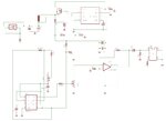
I use an opamp that requires a heatsink, now I want to put it in a confined space and use a package that has the board as a heatsink, but don't have much space on the board.

I'm looking for some general advice on what to do, for example can I use the copper of the ground plane as part of the heatsink? My circuit includes a 555 timer and I'm wondering if the heating would affect the capacitance of the board and thus the frequency?

Thanks,

Ant.
 

You can certainly use the copper of the PCB as a heatsink. It depends on how much power you are trying to get rid of and what the package is that is creating the heat. What device generates the heat, what package is it in and how much power?

I doubt heat will influence the capacitance of the board enough for you to notice. With an RF board it may be an issue.

Keith.
 
  • Like
Reactions: ants

    ants

    Points: 2
    Helpful Answer Positive Rating
Hi Keith,

You helped me with revison 5 of this board a while back, in particular the Max770 DC booster, this is revision 6, the board works well. I'm into the realm of adjusting for better operation rather than design changes. I've attached the schematic and board.

I don't have room for a conventional heatsink in the container and don't really need a huge heatsink because the device is intended for short bursts only but after testing it I should use one. The device is ultrasonic and operates around 100KHz.

I'll be using around 5 Watts perhaps up to 10 Watts, so the chip does turn off after overheating. The board is around 1/3 Dm so quite small too. Most of the heat on the board is generated by an opa548 opamp. I'll be switching to a package that is glued to the board.

I'd be greatful for an opinion.

Thanks,

Ant.
 

Attachments

  • rev6 schematic.jpg
    rev6 schematic.jpg
    79.8 KB · Views: 87
  • board6.jpg
    board6.jpg
    144.6 KB · Views: 79
Last edited:

Ant,

You presumably know the MAX770 isn't recommended for new designs?

If you can afford the space, you could obviously clip a heatsink to the OP548T.

If you go to the DDPAK version, I doubt you will be able to dissipate 10W, or even 5W continuously. There is a calculator here which gives a guide Heat Sink Temperature Calculator but it is for 1oz copper - most PCBs are 0.5oz which will affect things a bit. So, you could get 43C/W with 1sq inch of 1oz copper. Doubling the area won't give half the C/W. You could put heatsink on both sides & put lots of vias through. I don't know how much impact that would have. If it is anything like disc brakes you want the area of the the hole to be less than the area of the plating in the hole, although that is a bit of a guess!

To be quite honest, unless you need the height, I would stick with a heatsink clipped/screwed to the TO220. Heatsinks vertically off the PCB are far better than ones flat to the PCB and you can get some pretty compact ones such as AAVID THERMALLOY|HF35|HEAT SINK, TO-220, 11°C/W | Farnell United Kingdom or AAVID THERMALLOY|ML516-25-B|HEAT SINK INDIAN CHIEF TO220/252 | Farnell United Kingdom or even AAVID THERMALLOY|PF752|HEAT SINK, TO-220, 23°C/W | Farnell United Kingdom

Keith.
 
  • Like
Reactions: ants

    ants

    Points: 2
    Helpful Answer Positive Rating
Hi Keith,

I didn't know the Max770 wasn't recommended for new designs. The board is for a personal project/prototype, it wouldn't be produced in more than a half dozen units so if one or two fail I wouldn't mind so much. I haven't thought about reliability at this stage but the lifetime of the unit is probably just 10 minutes, I think it will last that but will test it to check for sure. It needs bursts of 30 seconds and with no heatsink is cutting out.

I am squeezed for space I have 30mm in height, 30mm in width and a bit more in length (but cant remember without measuring). I'm thinking along the same lines as you that it would be better to find a way of putting a standard heatsink on, maybe I could rotate the TO220 opamp or put it flat. On the otherhand I also have it in mind that as a demonstration model opening it up to reveal a clunky heatsink might not look good, a bit like opening up a gadget to reveal it crammed with batteries! I didn't know there were clip on heatsinks that is a good invention. I will get some of those and see if I can get one to fit, the opamp is about 8mm from a wall so I will have to try some different combinations.

Thanks for the reply,

Ant.

---------- Post added at 22:21 ---------- Previous post was at 22:04 ----------

There are a few other things about the same board for whoever may read.

I have an output capacitor on the DC-DC booster that is 150uF. This is supplying the opamp which itself has two input capacitors, a 10uF tantalum and a 100nF ceramic. I'm thinking I could leave the 10uF off the board but I'm not sure what it would affect.

How important is the control voltage capacitor on a 555 timer? I'm wondering if I could leave that off.

Cheers,

Ant.
 

Ant,

The MAX1771 is the recommended replacement. I am not sure if it an exact drop-in, but I assume you will be able to buy the MAX770 for a while.

Yes, you can also get heatsinks to lay on the board, but they take up more board area than allowing it to stick up. In general vertical ones have a lower C/W for a given volume (although that does depend on orientation - heat rises). If it is for short bursts you may get away with a simple lump of metal. It will heat up during use and cool down in the gaps.

Keith.
 
  • Like
Reactions: ants

    ants

    Points: 2
    Helpful Answer Positive Rating
I have thought about making my own heatsink from a simple piece of metal. Or shrinking an existing one with a saw. It is workable.

I was a bit worried the Max770 might go out of stock at farnell or similar because I remember I was going to use a different opamp and then found it went out of stock for 6 months. So I bought up 10 Max770's a few weeks ago, the price dropped from £4 to £2.60 for ten, so I was happy with that. I will check the Max1771 as a backup.

Thanks,

Ant.
 

Ant,

I would keep the decoupling capacitors next to the OP548. If the MAX770 output capacitor was very close to the OP548 then you could drop them, but it isn't. Sometimes when laying out PCBs I drop some decoupling capacitors if opamps end up very close.

I don't think you can leave off the CV decoupler on the 555, but you are using through-hole components. If you are short of space then I would use surface mount everywhere if possible.

Keith.
 
  • Like
Reactions: ants

    ants

    Points: 2
    Helpful Answer Positive Rating
I will leave those caps but perhaps switch them to surface mount, I remember thinking about switching the SE555 timer to the LM555 because it is surface mount, i think I have some of those and they are half the size. There probably isn't much else I could leave off the board so I can revisit surface mount now.

One other thing I need to test tomorrow is the voltage divider I have feeding the 555 timer. The values I used were 47K (FR4) and 100k (FR3) so I was expecting the voltage to be reduced to one third (about 5V) but it was 1.3V. I ended up shorting the divider out, I'm wondering if the 555 is somehow part of the divider network. I think I will have to juggle with values.

Thanks,

Ant.
 

You cannot really supply chips with a potential divider unless the current through the divider is a lot higher than the current consumed by the chip. You should also decouple the supply pin to the 555 in either case.

Keith.
 
  • Like
Reactions: ants

    ants

    Points: 2
    Helpful Answer Positive Rating
If you consider a board redesign to meet the thermal requirements, you could also think of an option to reduce the power dissipation in a more principle way.

Now you're feeding a square wave with variable amplitude to a power OP. You could also use a switched push-pull output stage with a variable supply voltage instead. The variable supply would be generated by a switched mode converter. In a variation, a fixed voltage with variable pulse width can be used to control the output amplitude.

P.S.: If you want 5V for the LM555, a small low power voltage regulator (e.g. 78L05) is the most easy and precise way.
 
  • Like
Reactions: ants

    ants

    Points: 2
    Helpful Answer Positive Rating
You cannot really supply chips with a potential divider unless the current through the divider is a lot higher than the current consumed by the chip. You should also decouple the supply pin to the 555 in either case.

Keith.

Hi Keith,

I hadn't thought about the values only the ratio but it makes sense that they are too high, I will try lower values to up the current through it. I think I left off the 555 decouple cap because as a piezo driver the piezo acts somewhat like a cap and smooths out the signal. I did some testing yesterday and the signal into the opamp is a clean square wave but as it leaves and goes into the AC coupling it goes quite jagged, i'm not sure why, but the piezo itself is a nice sine wave. Do you still think I need to put that back in later?

If you consider a board redesign to meet the thermal requirements, you could also think of an option to reduce the power dissipation in a more principle way.

Now you're feeding a square wave with variable amplitude to a power OP. You could also use a switched push-pull output stage with a variable supply voltage instead. The variable supply would be generated by a switched mode converter. In a variation, a fixed voltage with variable pulse width can be used to control the output amplitude.

P.S.: If you want 5V for the LM555, a small low power voltage regulator (e.g. 78L05) is the most easy and precise way.

Hi FVM,

I think that would work and save power, you did give me a good idea on how to get this circuit working a while ago, so this info has been stored for later, thanks. I've tried the board in its container and taken some pics, the container isn't finished but its dimensions won't change, I have a bit more room than I thought, so I should try to find a clip on heatsink and test before a redesign. The opamp is on an angle because it has been reused a few times and one of its pins is shorter than the others now.

Thanks,

Ant.
 

Attachments

  • containerJPG.jpg
    containerJPG.jpg
    510.6 KB · Views: 76

I have ordered some heatsinks, I think one of them will fit and this will be ok. I'm testing the board with a vertical heatsink and still the ground plane gets quite hot, so it probably wasn't such a good idea to use the board. Piezo's are very power hungry so it is like a little radiator running and could keep me warm this winter. The batteries get quite hot too. I'll be putting 5 Watts on the piezo for sure, I'm not sure how much will be wasted as heat, probably another 2 or 3W

The 555 timer does need a decouple cap, I can see a quite noticeable ripple on the supply and think that would be prevented, it is probable I will reorder very similar boards at some point so I can add that then, it may be that I will have to centralise the opamp to allow room for a heatsink I can do that too. I'm still not sure why the relatively clean signal that goes into the opamp goes through the AC coupling and comes out uneven, it is something I will investigate.

I have also ordered some different resistor values, I'm missing a few which I will need to tweak the performance. I'm targetting an output of 200Vpp so I think I can reduce the output of the DC booster by 2 volts, I can also reduce the 555 timer output a little further and up the volts with the amp.
 

I've started on revision 7 now. Does it ever end? :) I was AC coupling with a through hole cap, it had an ESR of 2 ohms, not much less than the transformer it is feeding. I will have to surface mount that with a low ESR cap, move the opamp to enable use of a fixed heatsink and add the 555 decouple.
 

Status
Not open for further replies.

Similar threads

Part and Inventory Search

Welcome to EDABoard.com

Sponsor

Back
Top