Continue to Site

Welcome to EDAboard.com

Welcome to our site! EDAboard.com is an international Electronics Discussion Forum focused on EDA software, circuits, schematics, books, theory, papers, asic, pld, 8051, DSP, Network, RF, Analog Design, PCB, Service Manuals... and a whole lot more! To participate you need to register. Registration is free. Click here to register now.

using a thermister for temp reading

Status
Not open for further replies.

aliyesami

Full Member level 6
Joined
Jan 7, 2010
Messages
369
Helped
0
Reputation
0
Reaction score
0
Trophy points
1,296
Location
USA
Activity points
4,190
i bought a salinity probe from Oakton which comes integrated with a temperature cable, I just learned from their engineers that they use NTC 30K thermistor. If i look at the data sheet of this thermistor i see large lookup tables between resistance and temperature.
also the temperature have a degree gap in it.
so people interfacing this thermistor have to do a lookup into these large tables for every temperature reading unlike the temperature chips like LM60 which has formulas that can be used to convert the read signal into temperature values with precision of 100 units.

thanks

https://www.vishay.com/docs/29118/ntcle203.pdf
 

People use either a logarithmic function to represent the thermistor characteristic or table interpolation. You don't need much table points to achieve an appropriate accuracy, may be 8 or 16.
 
As you are measuring water temperature, the range of measurement is very unlikely to be outside the 0C to 40C range.
As FvM says, just make a lookup table with maybe eight values, say each five degrees.
Then interpolate between those.
 
im wondering what are the missing component to make NTCLE203E3...SB0 a complete thermister
 

Hi,

What does the salinity probe datasheet say? Is the thermistor resistance/temp. vital to the required % accuracy you want, if you're lucky and you don't need 100% precision - and it doesn't veer off into high % inaccuracies - maybe you can skip it, depends on each application.

Although looking at the thermistor datasheet resistance/temp table, good luck with that one, there must be a pattern there, it's lower and lower resistance gaps with higher temp... :)

Any conversion formulas like with humidity sensors, that show more accurate 0 - 100% (of something) measured to help decide if:
a) degree of inaccuracy over temperature (if you prefer to ignore the thermistor look up table) will matter to your application;
or
b) you can find a happy/unhappy midpoint - like sloppy calibrating to accept a degree of upper and lower end error with an ADC or any device with not precisely linear gain?

I have a humidity sensor that says 3% to 10% inaccurate if you don't include temperature in the calculation, the 10% part is at low temperatures, then again at higher temps (up to a limit, but I don't live in a 75ºC place!), so it's accurate enough for gardening, for example, but I doubt for a quality cigar case in a shop, to monitor a Rembrandt in a museum or a hospital sensor...

What do you need this salinity probe for, again? You said for a well or similar, I seem to remember.

If not then posts #2 and #3 are sensible suggestions, as you may have a good idea of upper and lower temp range.
 
hi d123
i have a separate temperature sensor based on LM60 which is pretty accurate but if i could use the one on this salinity probe it would be nice since its integrated .
i am needing this salinity probe and temp sensor for my aquarium.
the temp range would be from 70 to 90 deg F.
 

Hi,

Oh - you have a saltwater aquarium. That temp range isn't painful to calibrate is it? :) ºF to ºC is [(ºF - 32) * 5] / 9...

70 - 32 = 38; 90 - 32 = 58.
38*5 = 190; 58*5 = 290.
190/9 = 21.1ºC; 32.2ºC.

Great (maybe?): we only care about lookup from 20 - 35ºC!

You only need to suffer that look up table for minimum three, ideally four resistance values.

2507 - 1416 ohms. Not precise, but gives about 1091 ohms from 20ºC to 35ºC.

1091 ohms/15ºC = ~73 ohms per ºC (72.7333 to be precise). Wouldn't that be a measurable voltage, even if tiny in mV?

I'm not sure how you could use that with the salinity probe, but hope it is of some help...

Thinking off top of head, or probably not thinking enough - would a summing (or multiplying, logarithmic, or something along these lines) configuration op amp be a way of combining the voltages both sensors will create to get a value/voltage that is usable? I know the multiplying op amp circuits look like "a lot of" parts, but still.

If you use PICs, etc., then I hope calibrating is a lot easier for you.
 
The temperature range is so small, just straight line temperature compensation would probably be accurate enough.
 

im wondering what are the missing component to make NTCLE203E3...SB0 a complete thermister

You require another resistor. Preferably 1%.

That resistor forms a voltage divider with the thermistor. As the temperature changes, the thermistor value does, and therefore the divider's output voltage.
The way I've selected the resistor value that has worked well for me, is that which is equal to the thermistor's middle range.
For instance, if you only require to measure from 20 to 30 C, select the 25C value, which in your case is 2060 ohm. Therefore a standard 2050 ohm, 1% resistor would work.

If your microcontroller's ADC can have its reference voltage tied to the Vdd supply (most do), then the divider's output becomes ratiometric, and conversions become very simple.

you mean I would put this resister in parallel with the temp probe inputs or in series ?
can you please draw it out for me and from where I will tap the input for the ADC.
yes my micro can reference the ADC with 3.3v .
 

Hi,

It goes in series, and you connect the ADC input to the junction of the two resistors. You'd have to decide which way round interests you, thermistor on top would give rising voltage with temp I think.

e.g. (sorry for hieroglyphic representation)

+V
l = resistor or thermistor
_______> = ADC input

l = resistor or thermistor
0V
 

if I connect one end of the resistor to the thermistor where do I connect the other end of this resistor to ?
 

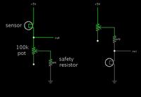
Typical sensor arrangements (as described in post #11).


The potentiometer indicates that you need to make adjustments until you are in a workable operating range. The value does not have to be close to 100k ohm. For instance, posts 7 & 9 suggest values in the 1k or 2k range.
 

if I connect one end of the resistor to the thermistor where do I connect the other end of this resistor to ?
I believe the question has been answered by schmitt trigger in post #9. Apparently he didn't mention clear enough the obvious point that the resistor must be connected to the same voltage that's used as ADC reference, usually just VDD.

Adding variable resistors etc. just ruins the accuracy.
 

Status
Not open for further replies.

Part and Inventory Search

Welcome to EDABoard.com

Sponsor

Back
Top