Continue to Site

Welcome to EDAboard.com

Welcome to our site! EDAboard.com is an international Electronics Discussion Forum focused on EDA software, circuits, schematics, books, theory, papers, asic, pld, 8051, DSP, Network, RF, Analog Design, PCB, Service Manuals... and a whole lot more! To participate you need to register. Registration is free. Click here to register now.

Using a germanium diode in the ground pin of a regulator IC.

Status
Not open for further replies.

scofmb

Newbie level 6
Joined
Sep 20, 2005
Messages
11
Helped
0
Reputation
0
Reaction score
0
Trophy points
1,281
Activity points
1,356
Hello!

I was wondering if i can add a germanium diode to a power supply on a devboard i have..i need to increase the voltage on the devboard by 0,3 since i'm getting undervoltage messages all the time from a SIM900 IC.
The sim900 datasheet say it could take a current over 1.5A, so i have to take that into account too.

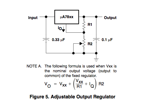
The current power supply sch are
actualpowersupply.jpg

I wonder if something like this would work
iwantpowersupply.jpg

Would it work? I didn't design this devboard so i found about this problem after i got it.

Thanks in advance
 

I think it will work if you reverse the Ge diode. It should be operated in forward, not in reverse direction as shown in your 2nd image.
 

Thanks, you are right, i have to put the way you said... but i never saw a schematic that does this and there must be a reason why nobody does... but couldn't find anything in google or here that talk about this. I don't want to mess this devboard because its the only one i have.
 

There are various ways to 'trick' a voltage regulator IC into providing a different voltage. Many of these methods involve putting a potentiometer across strategic spots.

It's only by chance that you found that a .3 V germanium diode will help you out in this case.

Something else that can be done is a silicon diode inline with the 4V supply (assuming the diode has a .65 V threshold). You won't need the regulator IC. This will give you about 3.3V at your device. If it's a little low then you'll look for a different diode which has less voltage drop.

Or if it's a little high you can add a series resistor to take up a little more V drop. Regulation won't be quite as good, however, if your load resistance varies much.

Take the above with caution if there's a chance your device could be ruined by under or over-voltage.
 

I don't want to mess this devboard because its the only one i have.
You won't damage anything with this method. But you pass on the Ge diode's temperature dependency to your output voltage.

i never saw a schematic that does this and there must be a reason why nobody does... but couldn't find anything in google or here that talk about this.
A correspondent method using a resistive divider to increase the output voltage has been suggested for many 3-terminal voltage regulators, see e.g. this circuit suggestion for the 78xx regulator series: . The resistor divider method avoids inheriting the temperature dependency.
 

Think that you'll find that the non-use of Germanium Diodes in series with the 'ground' leg of Voltage Regulators relates to their relatively high forward resistance as well as their Temperature dependency.

The method described by erikl can be resolved down to two fixed resistors, one between the output pin of your regulator to the ground pin and the second one from the ground pin to zero volts. The application note from the manufacturer of your Regulator IC will give information for the current which flows in the Ground pin of the IC you are using to calculate suitable resistance values.

As an aside, I use the high forward resistance characteristic of Ge Diodes to achieve 'rounded clipping' to limit audio signals.....

hope this assists
Mik
 

Status
Not open for further replies.

Similar threads

Part and Inventory Search

Welcome to EDABoard.com

Sponsor

Back
Top