Continue to Site

Welcome to EDAboard.com

Welcome to our site! EDAboard.com is an international Electronics Discussion Forum focused on EDA software, circuits, schematics, books, theory, papers, asic, pld, 8051, DSP, Network, RF, Analog Design, PCB, Service Manuals... and a whole lot more! To participate you need to register. Registration is free. Click here to register now.

Useless digital engineer having comparator problems

Status
Not open for further replies.

graeme_cunningham

Newbie level 3
Joined
Sep 29, 2010
Messages
4
Helped
0
Reputation
0
Reaction score
0
Trophy points
1,281
Activity points
1,320
I'm a digital engineer and have what I thought I thought would be a relatively easy analogue electronics problem to solve for an application I'm working on. But I'm having problems getting started.

I have two signals. The first is the "gate" signal. It will normally be 0v but will occasionally generate a pulse. The width of the pulse can vary.

During the time when the gate signal is above a specific value, a fixed width pulse should be generated on the next zero crossing of the 2nd signal

(I don't yet have the device that will generate the signals so can’t say what specifically

I've been able to use a Schmitt trigger some useful signals but tying it all together has got me stumped.

G
 

Didn't understand the question?
What do you want exactly?
[Q] During the time when the gate signal is above a specific value, a fixed width pulse should be generated on the next zero crossing of the 2nd signal
[/Q]
This can be done by a timer IC.. IC555
 

It might help you to draw out the expected input and required
output waveforms, and perhaps some of the envisioned
intermediate steps. This might make things clearer in your
mind.

Your fixed width output pulse wants a "one-shot" or
"monostable multivibrator", presumably with a non-retriggerable
input option.

Zero-crossing wants a comparator to drive this one=shot's
trigger input. The one-shot will likely have an enable so
you can use that, via another comparator if necessary,
for the "gate" (watch the polarity, many old-school
logic parts are active-low).

A Schmitt will be fine if input signals are unipolar and
remain within the spec'd logic input voltage range. A
comparator may allow you to accommodate more input
range, abnormal conditions etc., with divider networks
and clamps and such. The lesser accuracy of a Schmitt
logic device would be a problem in such cases.
 

I think what you are needing is two comparators (or one and a zero crossing detector) with the first one acting as an enable signal for the second. If I understand, if the gate is above a certain threshold, it allows the zero crossing detector to trigger a monostable (in hardware or software) and generate a pulse. It the gate signal is too low, nothing happens at all. Is this correct?

Another question: if the gate signal stays high for more than one zero crossing, should another pulse be generated or should the circuit inhibit after the first pulse?

The term 'zero crossing' suggests the signal will have a positive and negative part, do you need it to handle both or will any voltage close to zero, regardless of polarity be OK as a crossing point? I'm thinking that if all you need is to know when the signal is very low, you may be able to use a bridge rectifier so the polarity is always the same, it simplifies the electronics that way.

Brian.
 

Thanks for the replies so far.

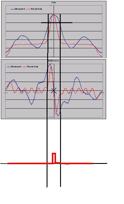
I have a diagram to hopefully illustrate my requirements better and below are a few comments to some of the questions raised.

The signals will swing around the mid point of the supply so for a single +5V supply what I actually want is when the signal crosses 2.5V

Only one pulse should be generated after the gate is activated any other transitions should be ignored.

It's also worth noting that in the example shown the signal crosses from "positive" to negative" but could also transition from "negative" to "positive".

Generating an active low signal wouldn't bother me.

Thanks again

---------- Post added at 11:24 ---------- Previous post was at 11:23 ----------

Sorry had to put it in a seperate post because I am a newbie
44_1286187757.jpg
 

Status
Not open for further replies.

Similar threads

Part and Inventory Search

Welcome to EDABoard.com

Sponsor

Back
Top