Continue to Site

Welcome to EDAboard.com

Welcome to our site! EDAboard.com is an international Electronics Discussion Forum focused on EDA software, circuits, schematics, books, theory, papers, asic, pld, 8051, DSP, Network, RF, Analog Design, PCB, Service Manuals... and a whole lot more! To participate you need to register. Registration is free. Click here to register now.

Use RF 100MHz to measure soil moisture IC generator plus IC detector

Status
Not open for further replies.
Does your soil have no salts or minerals like Styrofoam beads?
Are you watering it with pure distilled water?
If the above is false then simple AC resistance measurement of the soil will show if it is damp or dry.
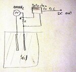
 

Sir, this is a development for open source soil sensor, should be compactible with all soils, but should measure only water content and not water content plus minerals.
The diference sensor 100MHz to 1MHz for example is that at 1MHz all signal is reflected by minerals in water. So you will be measuring water plus minerals, not only water content. If you go to 100MHz minerals does not affect measure, minerals have RF transparency at 100MHz. Precise measure only water content.
 

Return loss bridge at 100MHz usind AD8307 RSSI power meter

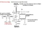
Hi, my ideia is to have a variable capacitive sensor on variable surrounding dielectic. But operating at RF 100MHz and measuring returned losses to get output DC. The capacitive probe will have from 10pF dry to 1000pF in wet dielectric.
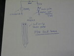
The circuit ideia is this on ths picture:

soil probe RF.JPG

The detector will measure return losses from this capacitive probe on media. (The ideia is to have RSSI variation proportional to dielectric changing air equal 1, soil =20 to 100 )
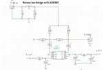
I found IC AD8307 good to measure RSSI signal to DC output. Here is a return loss circuit (only the ideia, must be redesigned).

return loss bridge.jpg

This is simplify return loss circuit:

return loss.JPG

AD8307Circuit.png


Impedance matching network is not very easy. But I'm going to use LTC6905 oscillator at 100MHz at input and output is going to capacitive probe (variable from 10pF to 1000pF) But now all matching network needs to be changed. Can someone help me?
The LT6905 ouputs 3Vpp 100MHz at 500ohm load . Will be this too much voltage?

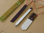
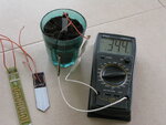
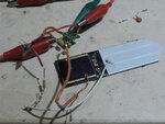
Here are probes I tested with capacimeter. One of them was developed by me using zigbee outputing 4MHz to measure probe capacitance.
But now need 100MHz for some specific aplication.

IMG_4593.JPG

IMG_4575.JPG

plate field.jpg
 
Last edited:
Hi, check the new technical document from the capacitive soil sensor.
 

Attachments

  • capacitive sensor wheatsone bridge return loss bridge.pdf
    503.7 KB · Views: 225
Last edited by a moderator:
The link is this one. This one is updated.
 

Attachments

  • rf capacitive probe- return bridge loss 1937.pdf
    433.4 KB · Views: 228
Last edited by a moderator:
My RF soil probe prototype is working fine. Please check **broken link removed**
 
FDR soil sensor working. Probe range is 15cm to detect hand, few mV change. wet soil to dry voltage difference 300mV
Measuring soil volumetric water content 15cm radius. Using 80MHz
Salinity insensible.
Need to amplify this voltage output to get range 0-3V proportional out
AD8307 outputs 3V dry and 2,7V at wet soil (reflectivity of soil). Need to use ampop subtractor with gain and a voltage referece. to get output proportional 0-3V

IMG_4880.JPG

IMG_4881.JPG
 

Probably you are seeing RF absorption. You can use the same ideas like in light absorption.
 
Yes absorption/reflection. For light there is an examle ir ligh sensors with emitteur and receiver ir led's.
Paralell pcb plates act as small antena cylindrical pattern. It starts detecting hand reflection at 15cm. Maybe a 15cm antenna range..

field.jpg

Inside soil it measures moisture. Soil wet output ad8307 2,7V , soil dry output 3,0V interval 300mV between dry and wet soil.
I'm using tantalum capacitors so maybe some lost at 80MHz, with ceramic less imepdance.

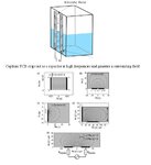
There is also a soil sensor with detecting rance

Figure-2-Principle-of-operation-of-the-FDR-sensor-left-6-7-9-and-idealized-volume.png
 

Does your soil have no salts or minerals like Styrofoam beads?.

Styrofoam beads are plastic- made from polystyrene- they are not naturally expected to be present in soil.They cannot be called salts or minerals.
 

Water salinity influence measures at low frequencuies. See this paper.

salinity influence.jpg

Most linear to measure and transparent to minerals is 380-485MHz range
 

Yes absorption/reflection. For light there is an example ir light sensors with emitter and receiver ir led's.
Paralell pcb plates act as small antena cylindrical pattern. It starts detecting hand reflection at 15cm. Maybe a 15cm antenna range..

It is unlikely to be reflection because at 100MHz, the wavelength is about 30cm and a bare hand will not be able to reflect any significant amount.

However, absorption remains the possibility. Presence of the hand nearby will load the antenna and this will be seen as greater dielectric absorption...

- - - Updated - - -

Most linear to measure and transparent to minerals is 380-485MHz range

True, but what the authors in the paper are reporting is the real part of the dielectric constant (lossy part) and happily ignoring the imaginary part of the dielectric constant.

The DC dielectric constant can be much different from the AC dielectric constant. Also note that the refractive index relation with the dielectric constant near some absorption band is often anomalous.
 

True, but what the authors in the paper are reporting is the real part of the dielectric constant (lossy part) and happily ignoring the imaginary part of the dielectric constant.
I agree that the quoted diagram emphasizes the importance of a complex impedance measurement. But the real part of ε is not the "lossy part", it's the imaginary part of permittivity that represent the losses https://en.wikipedia.org/wiki/Permittivity#Complex_permittivity

Unfortunately, the presented impedance measurement method doesn't selectively measure real and imaginary impedance components, just a scalar reflection factor.
 
Hi, for new design I recommend this setup.

IMG_4917[1].JPG

This will adjust better range because AD8307 is logarithmic. So find better range for probe on wet and probe dry. Adjust R until get most difference between wet to dry probe voltage output.
If you do not want 100MHz or 80MHz you can use any oscillator. I tested at 100khz with 2cm range. But not transparent to minerals.Good results only for tap water no nutrients added. 400ppm


Regards,
Vitor
 
Last edited:

Hi, for new design I recommend this setup.

View attachment 129297

This will adjust better range because AD8307 is logarithmic. So find better range for probe on wet and probe dry. Adjust R until get most difference between wet to dry probe voltage output.
If you do not want 100MHz or 80MHz you can use any oscillator. I tested at 100khz with 2cm range. But not transparent to minerals.Good results only for tap water no nutrients added. 400ppm


Regards,
Vitor

Hello , I want to ask how you are satisfied with the measurement of soil moisture ? it does not raise the temperature dependence ? Thank you
 

Re: 80MHz soil moisture sensor

One oscillator at 80MHz connected to one wire probe and other pcb wire connected to a detector?
Or is it using RC constant time and two pcb wires acts as capacitor, but injecting 80Mhz in circuit?

I guess it simply measures the impedance and converts the result to moisture content...
 

Status
Not open for further replies.

Part and Inventory Search

Welcome to EDABoard.com

Sponsor

Back
Top