Continue to Site

Welcome to EDAboard.com

Welcome to our site! EDAboard.com is an international Electronics Discussion Forum focused on EDA software, circuits, schematics, books, theory, papers, asic, pld, 8051, DSP, Network, RF, Analog Design, PCB, Service Manuals... and a whole lot more! To participate you need to register. Registration is free. Click here to register now.

USB question

Status
Not open for further replies.

Rajinder1268

Full Member level 3
Joined
Mar 20, 2021
Messages
162
Helped
1
Reputation
2
Reaction score
4
Trophy points
18
Activity points
1,228
Hi all,
I am tracking a board which has USB 2.0 requirement.
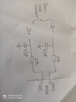
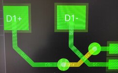
The USB to UART has the D+ and D- pins switched. This means that I am having to use vias in between the Micro USB connector and D+/- lines.
I have a 4 layer PCB, tracking on top, GND is 2nd, power is 3rd and 4th layer is for signals.
Are using vias going to be an issue. The track length difference between the diff pair is 2mm. It is impedance controlled at 90ohm.
I read that if the track length is less than 1/10th of wavelength of max frequency . The length of the tracking does not matter.

For usb high speed this equates to 20.5mm and low speed it is 165mm.
 

2mm shouldn't be a problem, nor should vias. But since you're now in the process of laying out the PCB, why don't you just fix the errors. I don't understand the problem.
 

2mm shouldn't be a problem, nor should vias. But since you're now in the process of laying out the PCB, why don't you just fix the errors. I don't understand the problem.
The only way I can keep the tracks the same length is to use vias. I will upload my layout snippet and schematic. I wanted to confirm that vias are not going to cause any issue, as one track is on the top layer and the other is routed to the bottom using a via then routed back to the top layer with a via.
 

Here is a snippet of the schematic and layout. I have measured the track length for D-/+ and the difference is 2.39mm. Note the tracking is from the right side of resistors to the ft device.
 

Attachments

  • IMG_20220905_095625.jpg
    IMG_20220905_095625.jpg
    1.5 MB · Views: 95
  • IMG_20220905_102118.jpg
    IMG_20220905_102118.jpg
    5.6 MB · Views: 100

Hi,

For this length ... it does not matter.

But anyways, if you are concerned about length differnce: Why do you route the longer trace to the opposite site to make it even longer? Use the shorter trace.

Klaus
 

Hi,

For this length ... it does not matter.

But anyways, if you are concerned about length differnce: Why do you route the longer trace to the opposite site to make it even longer? Use the shorter trace.

Klaus
I have already changed it so that the longer trace comes out of the resistor pad, then routes horizontally through 2 x vias. This makes the track length difference of D+/- to 1.65mm.
 

Status
Not open for further replies.

Similar threads

Part and Inventory Search

Welcome to EDABoard.com

Sponsor

Back
Top