Continue to Site

Welcome to EDAboard.com

Welcome to our site! EDAboard.com is an international Electronics Discussion Forum focused on EDA software, circuits, schematics, books, theory, papers, asic, pld, 8051, DSP, Network, RF, Analog Design, PCB, Service Manuals... and a whole lot more! To participate you need to register. Registration is free. Click here to register now.

USB Pic programmer problem

Status
Not open for further replies.

Ahmmed Razu

Advanced Member level 4
Joined
Jul 7, 2011
Messages
100
Helped
1
Reputation
2
Reaction score
1
Trophy points
1,298
Location
Bangladesh
Activity points
1,968
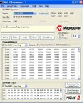
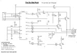
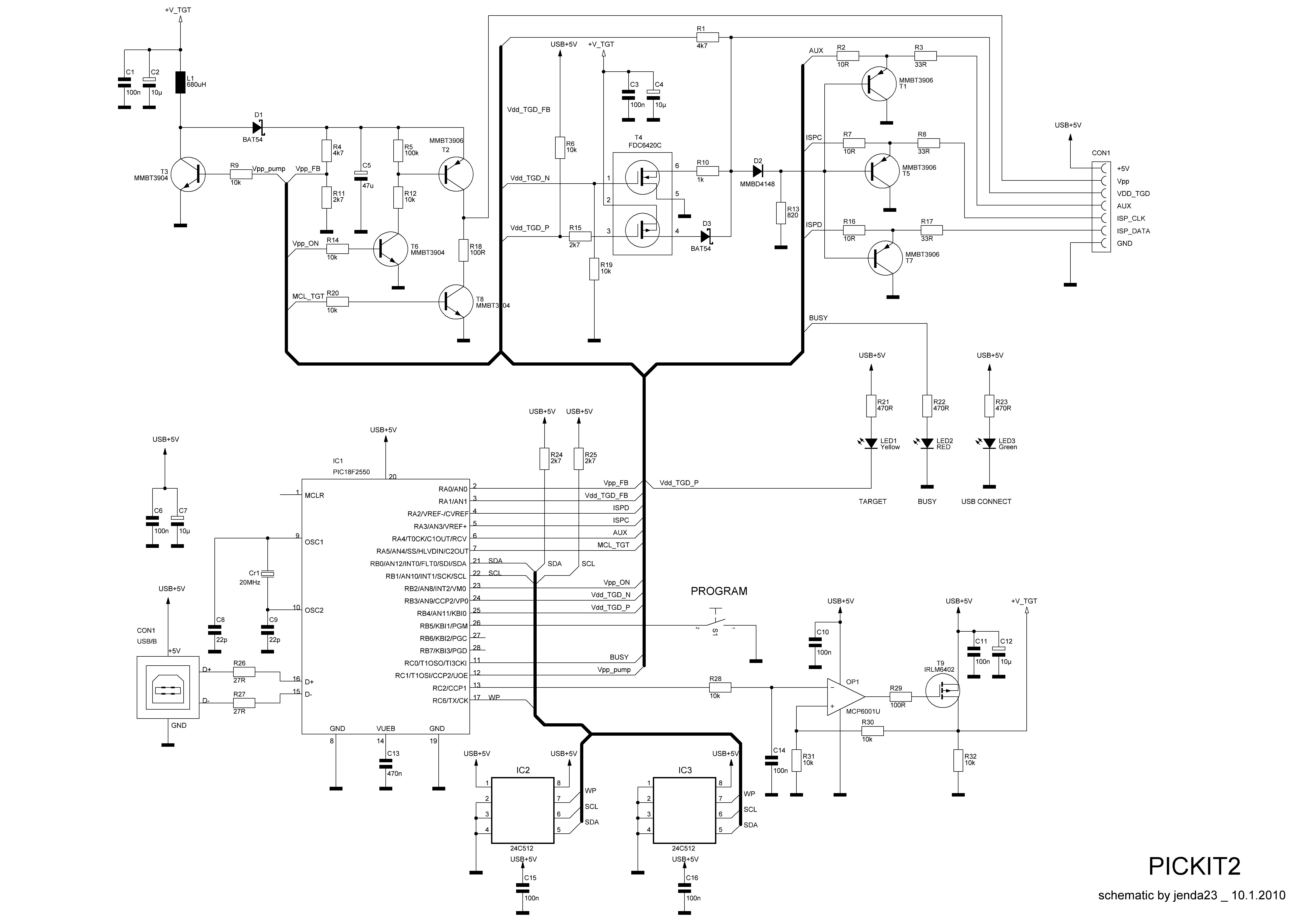
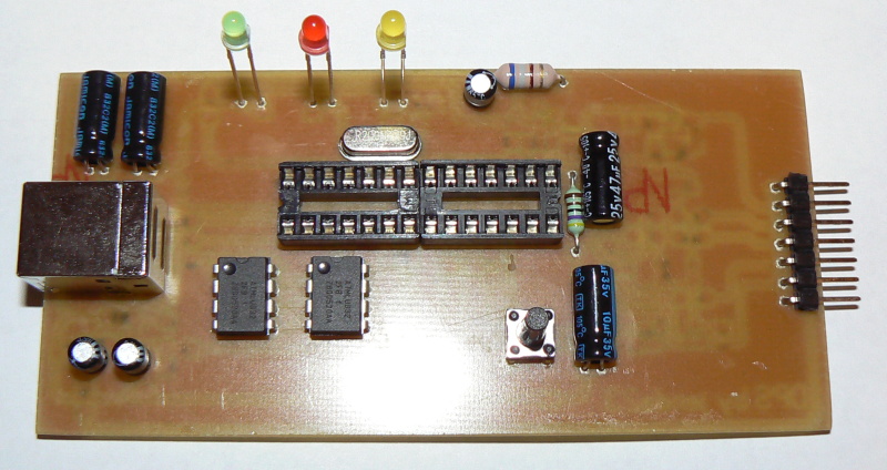
I am newer to PIC programmer. I want to make a USB PIC programmer.I searched in this forum first but i found a lot of confusion and there is no complete solution of this.i want to make Pickit2 programmer and i have downloaded the firmware(from microchip website) and other files in this purpose.when i extract the .rar file of firmware it becomes 90.85KB in size but i know that the flash memory of pic18f2550 where the firmware to be burned is 32KB so how is it possible to burn the firmware into pic18f2550? Suggest me.
 

In post #5 and #7 tpetar give PICKIT2 Clone thread is located here https://www.edaboard.com/threads/238365/

In fd-art2003.RAR is programmer for pic16f2550 and Winpic is in that thread.

Thats all you need.


I didnt have problems to make it from this files.
 

Hi,

Its just the way the pk2 hex code is packed in the the rar files.
As you can see it loads in with room to spare.

There are many, many versions of the Pk2 clone in this forum, just use the 'search'

Here is my circuit, many other similar ones in this forum with a pcb design as well.
 

Attachments

  • ScreenShot001.jpg
    ScreenShot001.jpg
    100.2 KB · Views: 182
  • minipk2.jpg
    minipk2.jpg
    66.6 KB · Views: 147

Hi,

Its just the way the pk2 hex code is packed in the the rar files.
As you can see it loads in with room to spare.

There are many, many versions of the Pk2 clone in this forum, just use the 'search'

Here is my circuit, many other similar ones in this forum with a pcb design as well.

Can you give me your firmware and device installation process?
I have PicKit2 version 2.61.Will it work with your given firmware if not which version i will use.
 

Can you give me your firmware and device installation process?
I have PicKit2 version 2.61.Will it work with your given firmware if not which version i will use.

Hi,

From what you said in your first post you have already downloaded all the software.

PK2 V2.61 is the stand alone PC programmer software, PK2V023200.hex is the PK2 program code that is burnt into the 18F2550 chip.

However think you might be missing the point, as well as those two programs you need a working Pickit2 hardware.

Thats the catch with building a PK2 clone, you need some other hardware to program the 2550 chip for the PK2.

If you search this forum for 'Pickit2 clones' you will see the also have designs for cheap diy jdm serail or paralllel progerammers for programming up the 2550.
Alternativley is there someone local who can program the 2550 up for you.
 

HEX files contains EEPROM, Flash, Boot loader data which together is greather then flash memory of uC what you see.

PICKit2 Clone works with PIC18F2550, also this programmer can program itself PIC18F2550 over Microchip PK2 V2.61, but PIC18F2550 first must have bootloader inself.

For first run you must program PIC18F2550 I suggest simple FD-Art2003 LPT programmer, but like wp100 says you just need to search and read edaboard thread related to this.

This is photo of my implementation of semi SMD double sided FD-Art2003 LPT programmer, its realy easy to make and use :

DSCF0089.JPGDSCF0091.JPGDSCF0092.JPG

PCB Bottom.jpgPCB Print Bottom.jpgPCB Print Top.jpgPCB Top.jpg

FD-art2003.jpg


-------

Ahmmed Razu to better understand HEX file size mismatch in windows, can you try this and see what happen :

1. Open WinPIC800 3.59
2. Go to File menu, select Open option, and load PK2V023200.HEX file, which have 90K in windows
3. Open File menu, select Save As option and save new file on new name

New file will have 76KB in Windows OS. ;-)

Use file comparison utility, simple from Total Commander File Compare tool, and see what additional free addresses you have in original file 90KB, and that addresses you dont have in new file.

Also open one by one file in WinPIC800 and look the same data in both files under Code, Data, and Settings tabs. You see the same data for both files in WinPIC800 software on all three tabs.
Windows size of HEX file is not accurate parameter to see amount of uC flash memory data. If you better look original or that new file whatever you will see lots of free addresses in Flash memory of uC. You see this file use about half memory of uC and in Windows have 90KB in size. The Hex file contains both data and the addresses at which to place that data.

Another : Open WinPIC800 and just perform Save As into new file, see 0KB Windows size, but file have 103bytes if you look better, because he is under 1K windows say 0KB in Explorer, also Total Commander and similar tools (this may depend from setting of particular tools, how to represent file size). Open with notepad that new file, and see what is inside. In WinPIC800 Code and Data tabs are empty, configuration not.
In that new "blank" file you should have thise :
:020000040020DA
:020000040030CA
:0E0000003FCF3F1F0087E5000FC00FE00F400D
:0200000400F00A
:00000001FF


Another : Open MS Word and type one sentence and save file. What is size of that file and why ? You just type few words in it. This file should be small according to ammount of data you enter in file, but when you check real size of file in Windows OS you see that is not the case. Why can you tell me.


Sometimes files among data what user enter, containts and other things like additional data, control and settings data. In case of HEX this can be data about all free adressess filled with FF. When you see size of file not all data for code data memory, some is for EEPROM, some for configurations bits.
For MS Word files and such thing files there is file structure with other things and informations about styles, fonts, settings of paragraphs, ........ + user data which user enter. Hex files dont have formating atribute about data like bold, italic,... its different data and format of file, I just whant to show you that not all like black and white. Also different HEX file variants exist with different file structure.

Data what you see in programmer software such WinPIC800 or PK2 2.61 exact that is written with their addresses to uC.


I hope I have given you a good explanation of this.


Additional info :
http://en.wikipedia.org/wiki/Intel_HEX
http://www.piclist.com/images/www/hobby_elec/e_pic5.htm
**broken link removed**
 
Last edited:
Hi Mr. tpetar
very helpful post.The above parallel PIC programmer, will work with 16F series while using winpic800 software?
 

Hi Mr. tpetar
very helpful post.The above parallel PIC programmer, will work with 16F series while using winpic800 software?

I'm glad that I help You.

This LPT programmer art2003 is made for PIC18F2550, I didnt try other chips on it. I dont know for PIC16F family I try just PIC18F2550. This is uC for PICKIT 2 Clone, and works fine. WINPIC800 can work with other programmmer also like JDM,... and can program program 12F, 16F, 18F...

When PICKIT2 Clone start works you can program lots of PICs see list :
 

Attachments

  • PICkit 2 Device Support List_1298130726389.jpeg
    PICkit 2 Device Support List_1298130726389.jpeg
    757.5 KB · Views: 80
Last edited:

Did you catch all steps and needed material for PICKIT2 Clone ?


I have files for PICKIT3 but its more complicated then PICKIT2. I dont think that you need this. PICKIt2 clone cover 8bit, 16bit, 24bit and even new 32bit uC.

This is Art2003 programmer web site:
**broken link removed**

This is PICKit2 Clone web site:
**broken link removed**


You ask for 16F.. do you need to program some 16F.. and because that you whant to build pickit2 ?


This can help you overview and user manual of pickit2 :
 

Attachments

  • PICkit2 Overview.pdf
    503.3 KB · Views: 105
  • PICKIT2 User Guide.pdf
    2.1 MB · Views: 71
Last edited:

I have files for PICKIT3 but its more complicated then PICKIT2. :


Hi tpetar,

Do you mean you have good files for a practicable PK 3 clone ? - if so would like to see a copy please.
 

Files are old what I have and I think that you also have this files :

KIT3.DDB
pickit3FW.hex
KIT3V01.pcb
KIT3V01.Sch

I think PICKIT3 Clone will come up on Internet very soon.
 

Hi,

Its just the way the pk2 hex code is packed in the the rar files.
As you can see it loads in with room to spare.

There are many, many versions of the Pk2 clone in this forum, just use the 'search'

Here is my circuit, many other similar ones in this forum with a pcb design as well.

In the above Circuit diagram the value of C1 and C5 is not clear due to the low resolution of picture, is C1=100uf or 100nf and C5=470uf or 470nf, give me the value please.Can you upload a high resolution picture? In your pickit2 board i can see that you are using a yellow LED.where are you using this? There is a comment on capacitor C7 but capacitor C7 is not available in the circuit diagram.Whats the matter? Is there any problem with configuration bits like AVR uc needed to change fuse bits separately? only loading the hex to it(PIC18F2550) will work, no need to change the configuration bits separately?
 
Last edited:

Hi,

Think you can see the values a bit better on this picture, have attached a bmp file which should be clearer.


The Amber led was on my original build but is not really used on a simple clone so was not included in the diagram

The Text reference to C7 should in fact be C6, will change that.

You just download from Microchip and program in the PK2V023200.HEX file, it contains all relevant config details, nothing to add or change.
 

Attachments

  • pk2hi.jpg
    805.7 KB · Views: 100
  • pk2hi.rar
    103.3 KB · Views: 82
Hi,

Think you can see the values a bit better on this picture, have attached a bmp file which should be clearer.


The Amber led was on my original build but is not really used on a simple clone so was not included in the diagram

The Text reference to C7 should in fact be C6, will change that.

You just download from Microchip and program in the PK2V023200.HEX file, it contains all relevant config details, nothing to add or change.

very helpful comment.But there is still another problem that is, two types of inductor value is observed ,680mH(in fig) and 680uH(in comment under the fig).Which one is correct and you used in your programmer, that i will use to implement this?Will 470uH or 470mH work properly? Please give me the correct value that you used in your programmer.
Thanks.
 

Hi,

Yes as Tpetar says it is 680 Uh, though it does work fine when I tried it with a 470 Uh.

If you open Pickit2 V2.61, in the Help section there is the Pk2 User guide, on the last pages there is the full ciruit diagram with component values.


In the mean time I shall go into a corner with my Dunces hat and rewite that diagram :oops::oops::oops:
 
Hi,

Don't know which one matches your programmer, assume you built the FD LPT one ? just select the first on the list and see if it recognises the chip, if not work down the list to find something compatible.
 

Status
Not open for further replies.

Similar threads

Part and Inventory Search

Welcome to EDABoard.com

Sponsor

Back
Top