Continue to Site

Welcome to EDAboard.com

Welcome to our site! EDAboard.com is an international Electronics Discussion Forum focused on EDA software, circuits, schematics, books, theory, papers, asic, pld, 8051, DSP, Network, RF, Analog Design, PCB, Service Manuals... and a whole lot more! To participate you need to register. Registration is free. Click here to register now.

USB interface with PIC18F4550.... help please.

Status
Not open for further replies.

akhter900

Junior Member level 1
Joined
Jun 7, 2009
Messages
17
Helped
0
Reputation
0
Reaction score
0
Trophy points
1,281
Activity points
1,456
Hello dear all........

Now I need to do another test.
I want to transfer some data (array of data) stored in PIC to PC using USB interface.

What I know that....I need to write
1) Firmware for PIC
2) GUI interface for PC.

I dont know how to do this. I want to use mikroC and C#.

Please give me your valuable ideas, suggestions and some useful links so that I can study and learn and do some experiment on it.

regards,

akhter
 

im facing the same problem ............take help from pic18f4550data sheet and ccs compiler usb code tutorials
 

any particular reason for using MicroC? I would use the Microchip compiler for PIC18s
**broken link removed**

with the USB framework which comes with functions to interface to the USB and plenty of example code, e.g. to connect a PIC18 to a PC host
**broken link removed**
 

It is very easy task to do this with microC and VB.NET for example. I did it many times. I'll try to help you. I made USB Joystick based on CDC-decoder (capacitor sensors).
But you will have to wait a little because all compilers and simulators installed only on my work laptop. And I forgot them in office. Please, be patient. I promise to help you.

---------- Post added 01-12-11 at 00:24 ---------- Previous post was 30-11-11 at 23:59 ----------

So, I can use my second laptop a little and we can start. Sorry for my english.
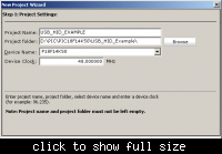
First of all, we need to start new project and choose a micro controller. I'm using PIC18F1xK50.
It is very low cost controller. But I must warn you. It not support debug functions.
You can choose PIC18F13K50, it support USB too, but it has two time less ram and flash memory. Flash memory not a problem. But after using HID Library you will able to use less then 20% free ram memory. Use this controller only with very simple tasks if you want to use USB HID.
So, we choosing PIC18F14K50.

To be continued...
Few words about clock frequency. For USB2.0 USB clock must be very accurate 48Mhz. Only high speed (HS) crystal accepted. You can use 6,12,24 and 48 Mhz crystals. We will use 12Mhz crystal with 4xPLL.

---------- Post added at 00:36 ---------- Previous post was at 00:24 ----------

Let's continue...
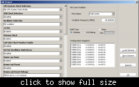
After the project wizard closed, we need to adjust configuration bits.

CPU System clock Selection
We can choose dividing main clock. For example, if we are using 24Mhz crystal, to obtain 48Mhz main clock frequency, we need to divide it by 2 and then use 4xPLL multiple.
MCLR Pin
Usually, I'm turning off this pin to provide digital functions on it. If you not using external watch dog or don't want to use reset chain, turn it off and let the MCU reset him self.
All other settings look understandable clear.

---------- Post added at 00:40 ---------- Previous post was at 00:36 ----------

Ok, the project ready. Let's start to use the library.
Lunch HID Terminal
Tools -> HID Terminal
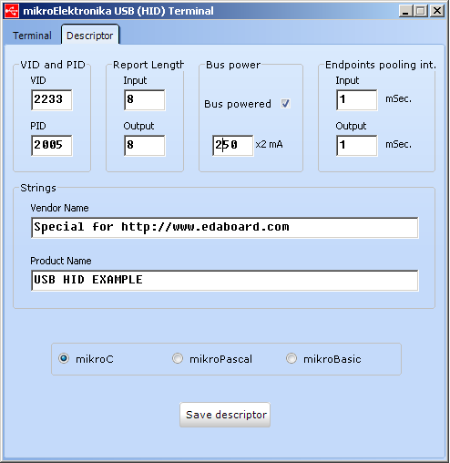
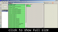
Choose Descriptor page.
3_1322691575.png


---------- Post added at 00:49 ---------- Previous post was at 00:40 ----------

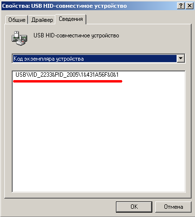
VID and PID - you device individual numbers. If you want to use it officially, you should prepare two thousand dollars for registration. Don't try do this in real life. You will be killed or seriously injured by your wife.
This numbers stored in HEX format. So, VID=0x2233 and PID=0x2005 for our example. We will use this values on PC part.
Report length - number of bytes that we will send to PC and read back.
Bus power - maximum current consumption that we able to use in our circuit in case of USB Power. Useful for USB Li-Ion chargers for example.
Endpoints pooling int.
Very important thing. I will explain how to use it for advanced users. Now we just leave it for 1 msec.
Vendor and Product name.
Write here what you want. This string you will see when the device will be connected to PC.
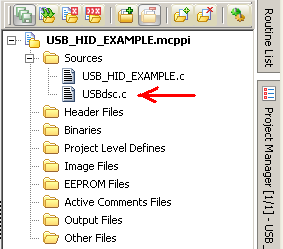
So, we are finished with descriptor. Lest save it in project folder and add this file to project.
39_1322691575.png


---------- Post added at 00:51 ---------- Previous post was at 00:49 ----------

Now we are ready to prepare our first program. Just use copy-paste my code. I will explain how it works.
Code:
 unsigned char readbuff[8] absolute 0x280;   // Buffers should be in USB RAM, please consult datasheet
 unsigned char writebuff[8] absolute 0x288;
 
void main() {
 char cnt;
 ANSEL=0;                                  // CONFIGURE ALL PORTS FOR DITITAL I/O
 ANSELH=0;                                 // NEVER DO THIS IN REAL LIFE. UNUSED PINS MUST BE LEFT ANALOG INPUTS
 HID_Enable(&readbuff,&writebuff);         // Enable HID communication
 while(1)
 {
    while(!HID_Read());

    for(cnt=0;cnt<8;cnt++)
      writebuff[cnt]=readbuff[cnt];

    while(!HID_Write(&writebuff,8));
}

}
void interrupt(){
   USB_Interrupt_Proc();                   // USB servicing is done inside the interrupt
}


---------- Post added at 00:59 ---------- Previous post was at 00:51 ----------

Now I will explain what this code do and how.
Code:
 unsigned char readbuff[8] absolute 0x280;   // Buffers should be in USB RAM, please consult datasheet
 unsigned char writebuff[8] absolute 0x288;
We declaring to local byte arrays for input and output data. As you can see, the array length is the same like in descriptor (8 bytes). This is mandatory.
What does 0x280 and 0x288 means?
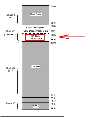
It is absolute address for store the usb data. To use the correct adress, we need to explore the datasheet (always read datasheets. It is like a bible for embedder!)
0_1322691575.png

The datasheet says that the USB RAM starts from address 0x280 and ends at 0x2FF. That means that we have 127 bytes for store the input and output data. Thats why you can't use array longer than 64 bytes.
Because our readbuff array 8 bytes long, we should use memory for writebuff starts from 0x288 address.

---------- Post added at 01:01 ---------- Previous post was at 00:59 ----------

Now we can connect our device to PC.
VDD -> USB VCC
D+ -> USB D+
D- -> USB D-
VSS - USB GND
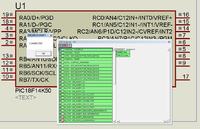
Or we can simulate it with Proteus with USB drivers installed. No difference. It will work too.

---------- Post added at 01:10 ---------- Previous post was at 01:01 ----------

After that we have a new device connected. Should I explain how to write and read data in program?
78_1322694498.png

If you want to use interrupts, I will explain how to separate it from USB Pooling Interrupt later. I need to find my examples.

---------- Post added at 01:15 ---------- Previous post was at 01:10 ----------

Special for moderators.
If you want that I continue this article, please, store my messages in FAQ or etc.
See in next series...
USB Joystick. It is easy!
Getting data from device using VB.NET
Transferring data from any pointer device to microcontroller throw radio transceiver. First step to build radio-controlled robot.
 
Attaching article files.
 

Attachments

  • USB_HID_Example.rar
    225.1 KB · Views: 250

    xpress_embedo

    Points: 2
    Helpful Answer Positive Rating
    V

    Points: 2
    Helpful Answer Positive Rating

    gldf

    Points: 2
    Helpful Answer Positive Rating
As I promised, code example to combine USB interrupt with TMR1 interrupt:
Code:
void interrupt (void)
{
     if (PIR1.TMR1IF!=0) {PIR1.TMR1IF=0; TMR1INT_Handle();}
     if (PIR2.USBIF!=0) USB_Interrupt_Proc();
}
 
Nice Explanation
I will surely try this...
But i am not having the full version of the MikroC Compiler...
Thats why i get Demo Limit Error
:-(
 

Thanks nice TUT,

I am using mikroC ver. 8.1.0.0 which version you are using in this TUT ? because I have not such a device in list that u r using here, and also non of USBdis.c file shown in source folder. . .
 

The code above is given for USBdsc.c is where to past in that file? there is number of written code here?
 

    V

    Points: 2
    Helpful Answer Positive Rating
Hello!! Easy Rider Can You tell me how to make GUI to send data and receive data from and to PC using Visual Basic.
For Your Code....
 

The code above is given for USBdsc.c is where to past in that file? there is number of written code here?
This code for main program. You no need to edit USBdsc.c. It was generated by MikroC
Hello!! Easy Rider Can You tell me how to make GUI to send data and receive data from and to PC using Visual Basic.
For Your Code....
Yes. Little bit later. It will much difficult. Wait, please.
 
Okay I am waiting for your next tutorial....

If possible kindly mail me... the GUI for this project made in Visual Basic...

As i am having rudimentary knowledge of Visual Basic.. so by seeing your code i can understand something.
 

Hello EasyRider When will you post your tutorial on Visual Basic
 

Ok, before we start, we need to install USB HID library that will help us introduce USB communication.
Just unpack and copy dll file to your windows/system32 folder. This is default windows folder where stores all libraries.
View attachment HID_Lib_Plus.rar
Than we will need Visual Basic 2008/2010 or whole Visual Studio.NET
This product you can download from official site for free.
Now, compiler installed, first project created and we are ready to work.
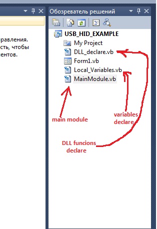
First of all, we need to sort all what we are trying to do. Everything must be on their place.
By selecting our project name right upper window, clicking right mouse button we can add an existing file or create a new one for our project.
We need a module where we will declare the HID Library functions.
74_1323093613.jpg

Open our new module and add this code there:
Code:
Module DLL_declare
    Public Declare Function HID_OpenDevice Lib "HID_Lib_Plus.dll" (ByVal PID As Integer, ByVal VID As Integer, ByVal VersionNumber As Short, ByVal Index As Short) As Integer
    Public Declare Function HID_CloseDevice Lib "HID_Lib_Plus.dll" (ByVal Handle As Integer) As Integer
    Public Declare Function HID_ReadDevice Lib "HID_Lib_Plus.dll" (ByVal Handle As Integer, ByVal buffer() As Byte, ByVal Len As Integer) As Integer
    Public Declare Function HID_WriteDevice Lib "HID_Lib_Plus.dll" (ByVal Handle As Integer, ByVal buffer() As Byte, ByVal Len As Integer) As Integer
    Public Declare Function HID_DeviceTest Lib "HID_Lib_Plus.dll" (ByVal PID As Integer, ByVal VID As Integer, ByVal VersionNumber As Short, ByVal Index As Short) As Integer
    Public Declare Function HID_GetInputReport Lib "HID_Lib_Plus.dll" (ByVal Handle As Integer, ByVal buffer() As Byte, ByVal Len As Integer) As Integer
    Public Declare Function HID_SetOutputReport Lib "HID_Lib_Plus.dll" (ByVal Handle As Integer, ByVal buffer() As Byte, ByVal Len As Integer) As Integer
    Public Declare Function HID_GetManufacturerString Lib "HID_Lib_Plus.dll" (ByVal Handle) As String
    Public Declare Function HID_GetProductString Lib "HID_Lib_Plus.dll" (ByVal Handle) As String
    Public Declare Function HID_GetSerialNumberString Lib "HID_Lib_Plus.dll" (ByVal Handle) As String
End Module
As you can see, now we have a functions to work with HID Library.

Ok, now go to the variable declaration module and declare the our first thread:
Code:
Public check_connection_thread As New System.Threading.Thread(AddressOf check_connection)
This will be parallel task that will check USB connection to our device.
Here we can add a constant variables that including info about our device:
Code:
    Public Const VID As Integer = 8755 ' decimal value of VID
    Public Const PID As Integer = 8197
    Public Const vers As Short = 1
    Public Const index As Short = 0

Now we can add this code to our MainModule:
Code:
Module MainModule
    Public Sub check_connection()
        Do
            If HID_DeviceTest(PID, VID, vers, index) <> 0 Then                                            
                MsgBox("CONNECTED!")
            End If
            System.Threading.Thread.Sleep(1000)
        Loop
    End Sub
End Module
Then we need to open the form code (by clicking twice on form in form constructor) and add this launch thread string:
Code:
check_connection_thread.Start()
3_FormCode.jpg
After this few simple steps our first project ready to be tested. If everything done properly, when device connected, message must appear.
 
Last edited:

Attaching VB2010 project.
View attachment USB_HID_EXAMPLE.rar
I will continue later. To read and write data we will need a handle. To get handle we need to check that USB device connected and handle not gotten already.
 
Thanks Nice Tutorial...
Hope it will work for me...
As it seems to be much more complicated..
Anyways Thank You So much
 

Hello easyrider can u help me for usb interface with pic18f4550 using ccs compiler......

---------- Post added at 21:09 ---------- Previous post was at 20:54 ----------

Hello easyrider can u help me for usb interface with pic18f4550 using ccs compiler......
 

Status
Not open for further replies.

Similar threads

Part and Inventory Search

Welcome to EDABoard.com

Sponsor

Back
Top