Continue to Site

Welcome to EDAboard.com

Welcome to our site! EDAboard.com is an international Electronics Discussion Forum focused on EDA software, circuits, schematics, books, theory, papers, asic, pld, 8051, DSP, Network, RF, Analog Design, PCB, Service Manuals... and a whole lot more! To participate you need to register. Registration is free. Click here to register now.

USB interface with leds

Status
Not open for further replies.

fael097

Newbie level 6
Joined
Jun 7, 2011
Messages
13
Helped
0
Reputation
0
Reaction score
0
Trophy points
1,281
Activity points
1,410
Hey,

I'm new to these forums, or to not-basic electronics in general, so I have no idea where's the correct place to post this thread, but in case it's not here, please move it to the appropriate section.

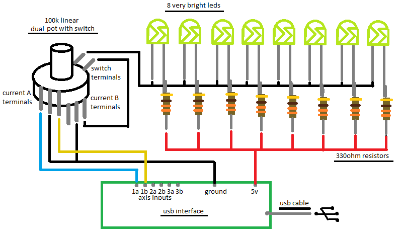
I'm creating a home made cockpit for playing flight sims, so for the first panel, I took the usb interface from an old joystick (12 buttons, 4 axis, POV hat, force feedback) and connected some switches to it. so far it's working, but I wanted to go further, and have some LED lights attached to a potentiometer that would control both real lights in my panel, and the lights in game through an axis.

So, I have some problems:

1st, I connected a regular potentiometer (I have no Idea how many Ks) to all my leds. it works sort of well, except they are always on, dim, but on, and also, they are not equally bright as I raise the intensity through the pot. when its on max/min, they appear to be equally bright, but not in-between.

this is the least of my problems, I bought a pot with a switch, and i resolved the problem of always on. about the difference of intensity, that doesn't bothers me that much right now, so I left it like that while I dont find a solution.

the bigger problems:

I wanted to connect the pot to the usb interface, not only to power. some guys told me if I connect the 5v and the interface on the same pot pin, it might damage the whole thing, and I'd need a dual pot. I even bought a pot with a switch, to be able to turn the leds off, but that doesnt help, since I'd need a dual pot with a switch.

since I don't have a dual pot atm, I disconnected everything, and tried to use the pot hooked to the usb interface, to see if I can control the axis. turns out that it simply doesn't work as the pots that come with the joystick. i only have a milimetric portion of the pot's rotation that affect the axis, the rest of it keep the axis on 0, and a tiny bit moves it to 1. (nothing compared to the 0 to 100 that I should have from the beggining to the end of the pot's rotation). I believe that's because I'd need a pot with specific number of Ks, and linear or logarythimic, but IDK what exactly, what I have, and not even sure if that's really the problem.

so I'd need a dual pot, with switch, certain number of Ks, and linear or logarythimic, dont know which one. turns out that I can't find any pots with all these attributes.

that's why I'm asking for help, I'm so confused about all this stuff. :-?

thanks in advance!
 

anyone? I really need help.

the question is:

is there a way to connect a potentiometer to a usb board, AND make the same pot control leds intensity, without being a dual pot? are there alternatives? if not, where do I find a dual pot with switch, 100k linear?
 

Depending on how the analog input circuit works, it may be possible to tap the slider voltage and decouple the output by a buffer amplifier. Measuring the voltage in operation would be a fisrt step.
 
thanks for your answer! I really appreciate.

well, to start with, the USB board, gives me a power supply terminal (that's used mainly to connect leds) of 5v. based on that, I connected 8 leds in parallel, with a 330ohm resistor hooked to each one of them. for now I just hooked a simple on/off rocker switch to the ground wire, to be able to turn leds on and off, but as I mentioned, my plan is to use a potentiometer with switch. (for now I'm ok with unequally dimming leds, maybe later I can consider PWM)

is there any other ways I should measure the voltage? and how?

thanks again.
Rafael
 

Dear Rafael,

Despite your detailed explanation, I read not once, but could not get clearly the problem.
If possible, could you attach some schematic diagram concerning the circuit you assembled ?

+++
 

Andre,
Sorry I didn't make myself clear.
here's a picture of the circuit I'm trying to assemble:
3_1307730841.gif


So I'm basically trying to use the same potentiometer as an intensity controller AND on/off switch for my Led lights (thats why the pot with switch), and also as a game controller, that controls a directinput axis through my USB card.

I didn't find that potentiometer I've draw in the scheme, so for now I'm only using a simple rocker on/off switch to turn led lights on/off, and a regular potentiometer to control my directinput axis trhough the usb card.

however this isn't good, because the controller axis controls in-game lights, and I wanted the same potentiometer to control my lights in-game and the real leds.
 

Now, I am who will say sorry, because I don´t know that kind of potentiometer.

+++
 

It seems like a simple stereo potentiometer with a switch, there are also some dual concentric pots like the ones used for volume and tone in old radios

Alex
 

well, I didn't find that potentiometer. I've found dual pots, and pots with switch, but never a dual pot with a switch, but some people told me there is one.

and that's the only way i could think to be able to control both real leds, and in game axis. but I also have been reported that 100k pots are default for USB directinputs, and that 100k pots wont be able to dim the leds properly. that's why I'm asking here for alternatives.

any ideas?
thanks.
 

I think that the 100k resistance will be too high anyway even a 10k will turn the leds off, it will provide about 0.3mA for all leds, and each led will share 1/8 of that.
Did you measure the voltage of terminal A center tap, if it gives a reasonable voltage range adjustment you could use it in a circuit to control the leds.

Alex
 

Add a transistor for controlling leds,
with different bias arrangement you can find right light effect for leds.

Like this...............
Emitter_Foll_Leds_01.jpg

Don´t need switch, pot. meter slide at zero >>> Ileds = 0.


KAK
 
Last edited:

thanks guys.
I was thinking of using a 100k pot, because I read somewhere they were default for game controller axis. didn't test though, perhaps 10k pots should work aswell.
and I also thought of using a pot with a switch, because the only pot i tested with my leds wouldnt turn them off. guess I tested the wrong pot, I don't even remember how many Ks it was.

so I guess I'll test a 10k dual pot, with a transistor then.

will report back when I finish

thank you again,
Rafael

---------- Post added at 16:41 ---------- Previous post was at 16:29 ----------

kak, forgive my ignorance, but my knowledge of current symbols is very limited (hence the 4yo kid drawing i posted)

I even tried a symbols table on google, but some are different, or doesnt make sense, so could you please label your scheme, if thats not much trouble for you?

thanks.
 

I think you should consider using PWM for this; You'll need to learn about mircocontrollers of course, but how it would work is that you will use all three terminals of the pot with one protection resistor at the middle terminal to create a voltage divider. This pot will act like a voltage reference, ( it will not actually be connected to the LEDs but rather a VCO within the controller.) You'll create a program for the micro controller to send pulses to the leds, and also pluses through a serial port for it to be controlled in game.

I recommend the Arduino Micro Controller; since it's the only one I currently own and have a text book for.

EDIT:

Another thing I would like to add is that do you really need to have two cockpits? The simulated one and the one you are trying to build? Couldn't you just fly the flight simulator with the cockpit turned off and your real one filling in for it?
 
Last edited:

I don't see the need for a complicated solution, a simple opamp can provide a constant current output based on the input voltage

led_constant_current.gif

I have used a sinusoidal input 0-5v shown in blue (left axis), the total output current is shown in red (right axis) and the current of a single led is shown in green(right axis).

Alex
 

@zanderist: Yep, I read about PWM, but as far as I understand, it works to get the leds to the same brightness, rather than having different levels, when dimming directly through the pot.
honestly, for now, I'm satisfied with the pot only. If I can get a pot that can turn the leds off without having a switch, then I'll be more than happy. then later I can think of a way to keep them more equal.
about the controller, I considered arduino, but after pondering, I went for a gp-wiz40 from groovygamegear, and a leo bodnar's with axis input support, wich are cheap, and will do the job.
and about the cockpit, well, you got me.
yes, my plan is to use the real cockpit only, but idk, i guess it's gonna be a long time until i finish it, so I'll probably use the virtual AND the real for some time. and also, it's cool to have something that controls both lol

so my question now, will the 10k pot be enough to turn my leds off and 100% bright? what's the difference if I use linear and log pots? because as I already mentioned, I had a pot that would never turn leds off, but keep them dim while on 0% of its range. don't know how many Ks though.

apparently leo bodnars usb interface is ok with pots from 1k to 100k, so it's up to the leds.

@alex: I have no idea whats an op amp, but I'm looking . If the objective is to maitain led's bright equal, then it looks more simple than the pwm, and should work. something to think in the future.

cheers
 

There are many tutorials on the opamp, one of the m is Operational amplifier - Wikipedia, the free encyclopedia
LM358 is a cheap 8pin device, my schmatic translates the input voltage to a constant output current, maybe you can use it directly from the center tap of the pot that goes to the axis inputs , this is why I have asked you to measure the voltage range of that pin, you may be able to do what you want with that single pot only.

Alex
 

regarding the pot, I bought some dual 10k pots to test, but they didn't fully turn the lights off. I don't need to put 2 currents on the same terminals now that I have a dual pot, but I need a way to turn lights off without a switch.

ideas?
thanks
 

so my question changed. I just want to be able to control led dimming properly with a pot, now, doesnt matter if through pwm, opamp, whatever, but I wanted to be able to have leds OFF when pot at 0%, and leds fully bright when pot at 100%. what would be the best way?
 

I still think that the schematic of post #14 is a very easy solution for your problem, the input is 0-5v and the output 0-80mA (for all connected leds)

Alex
 

I'll give it a try.
I really appreciate all your help, it's just that I'm new to all this stuff, so I don't really get some symbols.
I get the leds, ac, earth, resistors, but how about values, for example, R1 is a 5k ohm resistor? and Q1 is a pot? how about the big triangle?
 

Status
Not open for further replies.

Part and Inventory Search

Welcome to EDABoard.com

Sponsor

Back
Top