Vermes
Advanced Member level 4
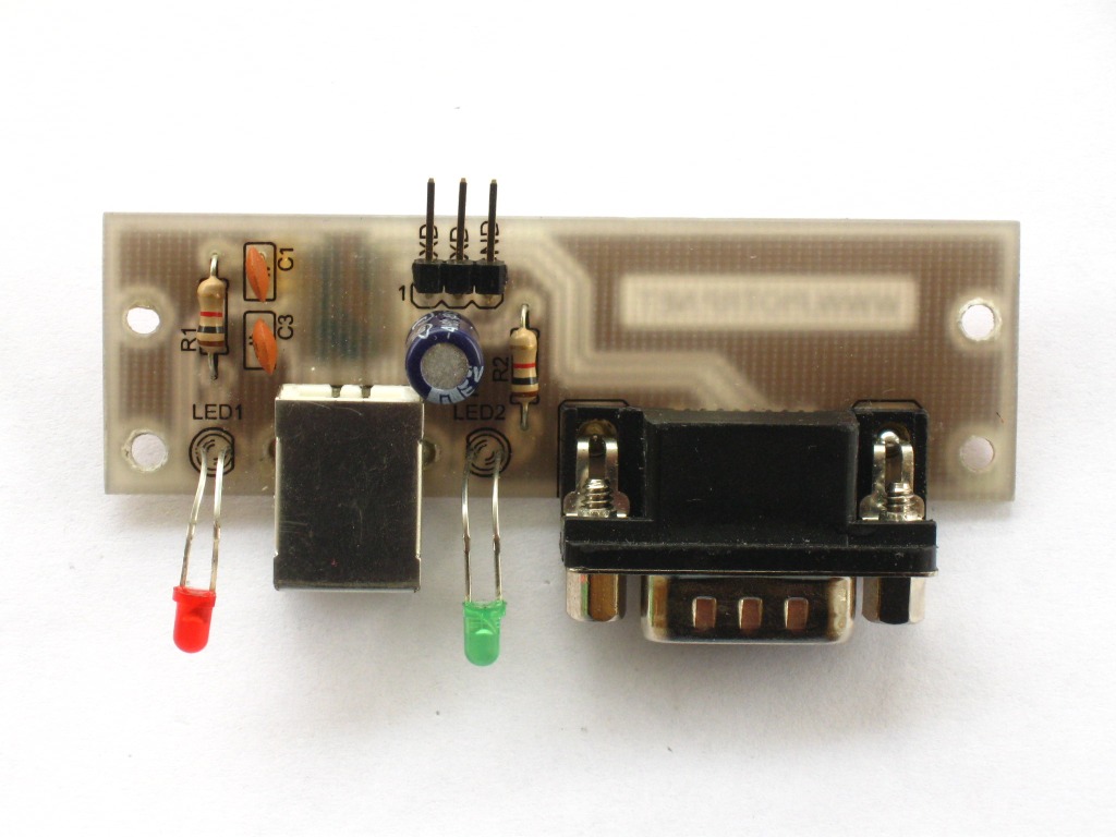
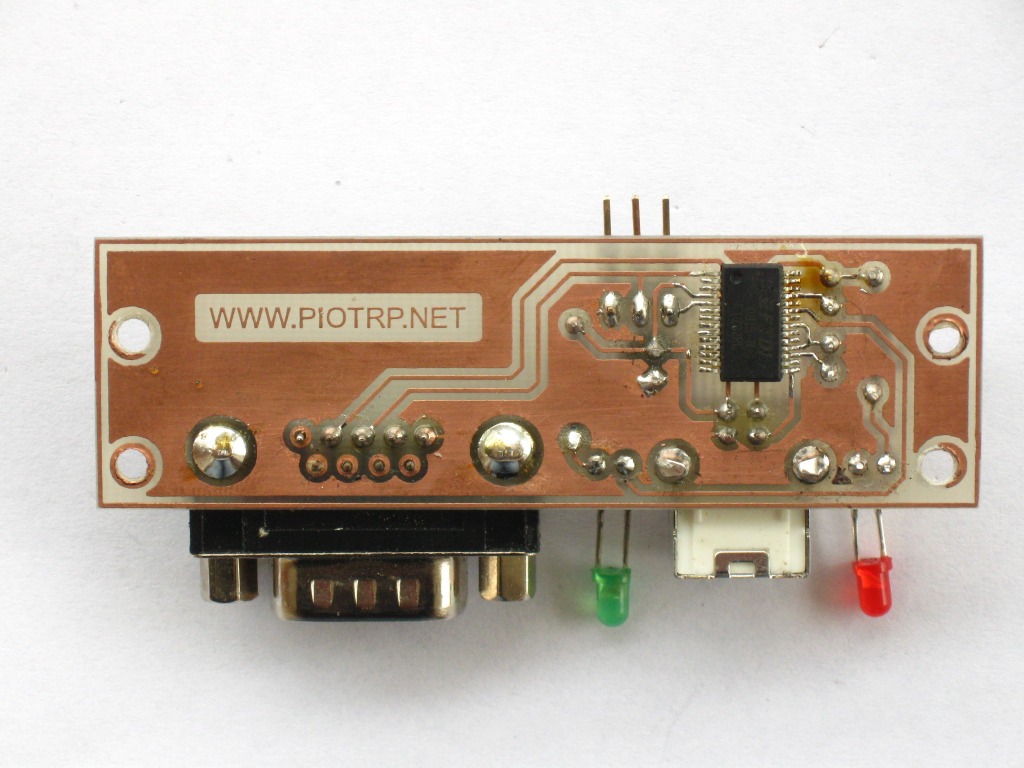
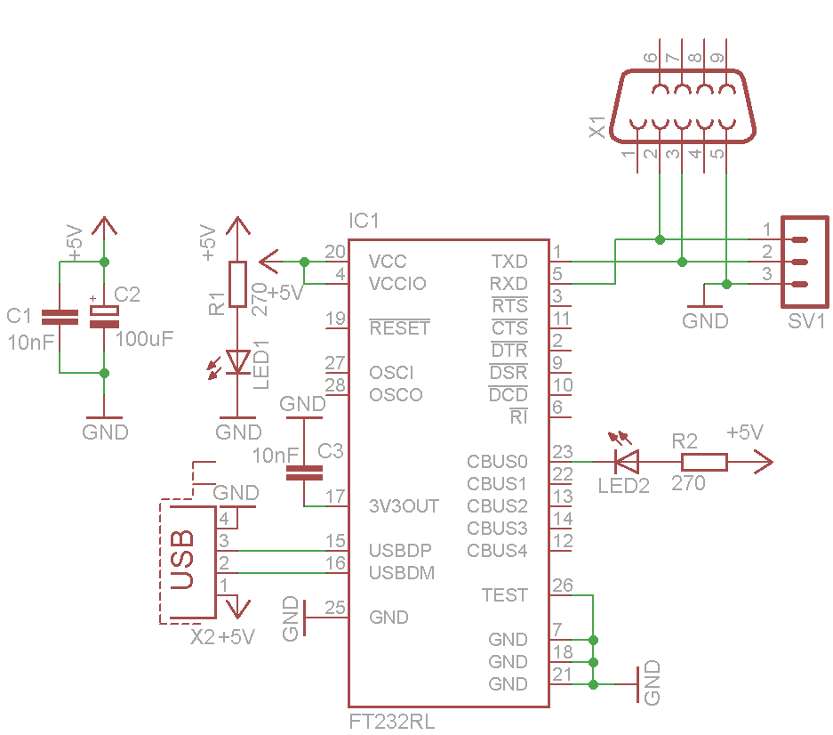
The communication module was based on system FT232RL fro FTDI Chip. RL version of the system did not require an additional EEPROM memory, so the converter can take less space. The module is powered directly from the USB port. The system consists of few pieces.
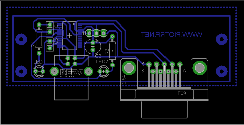
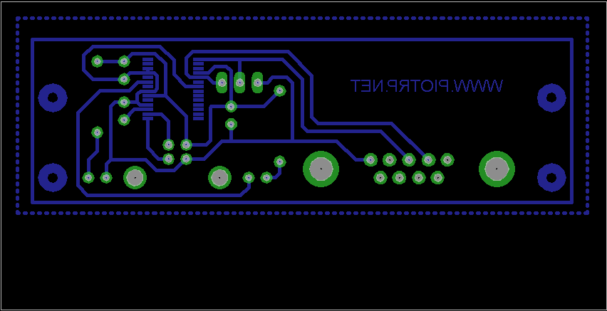
Capacitors C1, C2, C3 filter the supply. Diode D1 indicates the presence of the supply, while the diode D2 indicates transmission to/from the system. Microcontroller connections to the adapter can be done in two ways. It can be connected to SV1 or X1 connector. Connector X1 has the same pin arrangement as the COM port on the computer. Here LINK you can find the FT_Prog program, which allows you to change the settings of the FT232RL such as changing the polarization of inputs, changing the name and device ID, setting the functions of pins CBUS0..4 etc. The board has four holes to which you can screw a piece of curved plate and thus attach the module to the housing of a device.
Rar file with scheme and board in Eagle can be downloaded from **broken link removed**.
Link to original thread (useful attachment) – Moduł komunikacyjny USB