liteon
Full Member level 2
Hi,
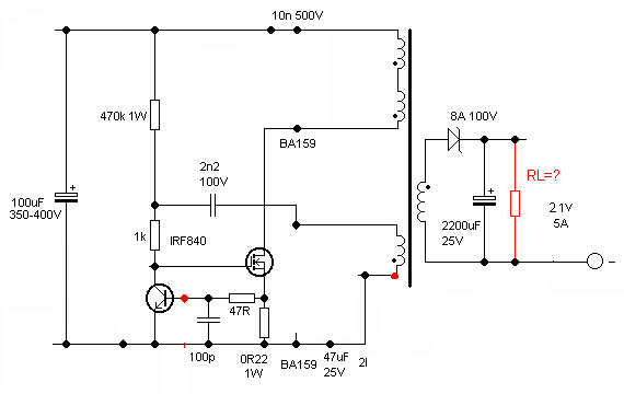
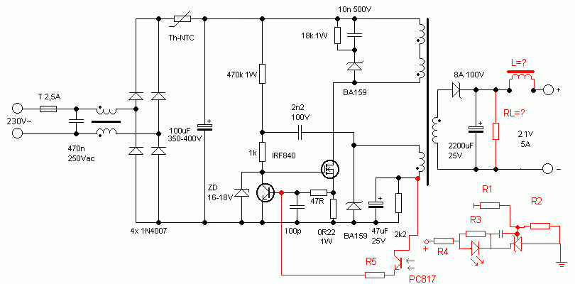
i need to figure out the working of following SMPS circuit.It is simple one mosfet based SMPS.
I want to make my first smps but first i need to ask few question to implement this project.
1- A little operational explanation.
2- Frequency depends on which part of the circuit.Can it be modified for different frequency.
3- How to determine the core types/size and number of turns for certain output say as in diagram 21v/5A.
4- How to determine the value of load resistor RL and inductor L at the output.
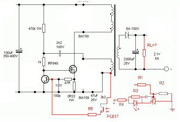
5- I want to regulate the out put voltage by using feed back loop circuit(colored red).How to configure the values of those resistors and capacitor.
i need to figure out the working of following SMPS circuit.It is simple one mosfet based SMPS.
I want to make my first smps but first i need to ask few question to implement this project.
1- A little operational explanation.
2- Frequency depends on which part of the circuit.Can it be modified for different frequency.
3- How to determine the core types/size and number of turns for certain output say as in diagram 21v/5A.
4- How to determine the value of load resistor RL and inductor L at the output.
5- I want to regulate the out put voltage by using feed back loop circuit(colored red).How to configure the values of those resistors and capacitor.