Seedz
Newbie level 2
Hi Guys,
this should be an easy one but i can't seem to figure it out:
I've got these LED trailer lights that i bought from China (there's the problem ;-) that were described as 12v/24v compatible but after testing then on my regulated power supply on 24V they didn't last very long:
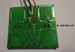
It's a very basic pcb design consisting of 16 LED's which are wired in series and parallel with some resistors and 2 diodes.
After researching it a bit it is obvious that this is designed around 12Volt input and would have never lasting long on the 24 volt motorhome it is intended for.
Does anyone know a quick way in changing the resistors and or diode so that i can withstand a constant voltage of 27Volt (that's what i got when the alternator is running)
See Attachment for pcd layout.
The pcd consist of 2 circuits where the constant voltage on the red wire would give you the "tail lights" which is limited by a resistor and the green light would bypass the resistor and provide the LED's with a higher voltage that gives you the "brake" lights.
So my first question is:
what is a safe voltage for 1 LED to have when i'm braking and my input voltage is 27Volts?
i tried to work it out and got this far:
R = E/I
E = Vbatt - Vled
I = 20mA
Vled = 2.1 volts
Vbatt = 27 volts
R=24.9/0.02 = 1245 ohms
The resistors that are on it at the moment are 100 Ohm and 570 Ohm in parallel creating effectively 85 Ohms over the circuit.
What resistors should i use to find the best range to drive these LED as a "tail light" and "brake light" circuit.
Thanks in advance,
sorry for the non technical English.
Sietse
this should be an easy one but i can't seem to figure it out:
I've got these LED trailer lights that i bought from China (there's the problem ;-) that were described as 12v/24v compatible but after testing then on my regulated power supply on 24V they didn't last very long:
It's a very basic pcb design consisting of 16 LED's which are wired in series and parallel with some resistors and 2 diodes.
After researching it a bit it is obvious that this is designed around 12Volt input and would have never lasting long on the 24 volt motorhome it is intended for.
Does anyone know a quick way in changing the resistors and or diode so that i can withstand a constant voltage of 27Volt (that's what i got when the alternator is running)
See Attachment for pcd layout.
The pcd consist of 2 circuits where the constant voltage on the red wire would give you the "tail lights" which is limited by a resistor and the green light would bypass the resistor and provide the LED's with a higher voltage that gives you the "brake" lights.
So my first question is:
what is a safe voltage for 1 LED to have when i'm braking and my input voltage is 27Volts?
i tried to work it out and got this far:
R = E/I
E = Vbatt - Vled
I = 20mA
Vled = 2.1 volts
Vbatt = 27 volts
R=24.9/0.02 = 1245 ohms
The resistors that are on it at the moment are 100 Ohm and 570 Ohm in parallel creating effectively 85 Ohms over the circuit.
What resistors should i use to find the best range to drive these LED as a "tail light" and "brake light" circuit.
Thanks in advance,
sorry for the non technical English.
Sietse