Continue to Site

Welcome to EDAboard.com

Welcome to our site! EDAboard.com is an international Electronics Discussion Forum focused on EDA software, circuits, schematics, books, theory, papers, asic, pld, 8051, DSP, Network, RF, Analog Design, PCB, Service Manuals... and a whole lot more! To participate you need to register. Registration is free. Click here to register now.

Underwater acoustic transmissions

Status
Not open for further replies.

BN77

Newbie level 4
Joined
Jun 13, 2015
Messages
5
Helped
0
Reputation
0
Reaction score
0
Trophy points
1
Activity points
61
Hi

I am new and this is my first post so please be gentle.

I am trying to make a system to transmit and recieve data underwater, or at this stage just something that will transmit an acoustic signal, a pinger, no more.
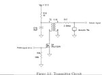
J Luan circuit.jpg

I found this circuit in a paper about the design of an acoustic altimiter.

https://www.google.co.uk/url?sa=t&r...=EgbjuhkqQnfy0tZPcvsZ9A&bvm=bv.99804247,d.d2s

I have purchased a cylindrical piezo transducer that i plan to use in place of the acoustic tile described in the paper. My cylinder has a capacitance of 6600pF and can take a voltage of up to around 1200v peak to peak. (I think I will aim for less than this at least to start with). I understand the need of a tuned reasonant circuit and think I can make a transformer that should do the job.

2 questions at the moment

1
The paper states that the circuit shown provide a little less than 500v peak to peak. How can this be? Surely a 12v supply and a transformer turns ratio of 1:19 will result in around 228v peak to peak.

2
How do I protect my micro controller from flyback voltage? Do I need to add a snubber diode somewhere? If so where and of what type?


I hope I have prepared this post properly I am not sure about the picture I tried to insert.

I will be very greatful for any assistance.

Cheers
 

The circuit in that thesis is poorly suited for its task...

One problem seen during breadboarding and testing the circuit was that
the FET was causing large voltage drops (7 or 8 Volts) in the 12 Volt power
bus whenever it turned on. Upon looking at the ID-VDS characteristic curve,
it was seen that whenever the FET was on, it would draw currents greater
than 3 Amps, which was the current limit on the power supply. This forces
the power supply out of its linear region of operation and the voltage drops
signiØcantly. As the FET switches on and oÆ with the PWM input, a large
ripple eÆect is created in the 12 Volt line.
One way to reduce the size of the ripple in the power line is to use
a diÆerent FET with a higher on resistance and a lower magnitude ID-VDS
curve. The new FET brings a signiØcant improvement to the circuit. It cleaned
up the 12 Volt bus and also increased the output voltage by 50 Volts peak-
to-peak. There was still, however, a small 2 to 3 Volt ripple that occurred
whenever the FET was being switched on and oÆ. As it turned out, this
was caused by the breadboard. The problem with using breadboards is that
the connections become very unreliable with high frequencies or high current
designs because the spring clips inside the breadboard have a small contact area
and can overheat quite easily. These white breadboards are only recommended
for circuits using less than 100 mA, but this part of the transmitter circuit
uses several Amps of current. Because of the high current in this design, the
resistance seen from the path connected to the 10uF capacitor became a good
amount larger than the path going to the power supply, so instead of tapping
the stored current in the capacitor, the FET was forcing current from the
power supply. To Øx this problem, a small 10 Ohm resistor is added between
the primary of the transformer and the 12 Volt bus to force the FET to use
the stored current in the low impedance capacitor before taking it from the
power supply. This addition smoothed the ripple from the 12 Volt line.
So they basically admit the circuit was drawing way too much current (because it is not coupling power effectively to the output), so they "fix" it by just increasing the resistance of the drive circuit. So they end up with a hugely inefficient driver, and don't even show any drive waveforms. Getting 500Vpp at the transducer is possible since the resonance between the transformer and transducer can provide voltage gain. But I wouldn't believe any specific claims by the authors given that they show no waveforms.
 

Commercial depth sounders are now rather common, and both the transducers and the circuitry to drive them should not present any revolutionary design problem.

Try to find out what equipment that transducer is used in and duplicate that.
 
Last edited:

The project described in the paper used a unusual high (and probably less suitable) echosounder frequency of 450 kHz. The resonance frequency of your transducer will be most likely lower. Transformer parameters and drive frequency have to be adapted.
 

I chose my particular transducer as it is one used by B Benson et al in this paper.
https://cseweb.ucsd.edu/~kastner/papers/oceans10-low_cost_modem.pdf

The paper gives some good clues but there is only a verbal description of the circuit used and no circuit diagram. Other searches have taken me in the same direction but details of actual components used is not there.

Electronics knowledge is very much my weak point. When I found the circuit in the J Luan paper with actual component numbers I thought I was getting somewhere but it seems from a post above that the circuit may not be as efficient as it could be.

I may try it anyway. I have a transformer already built from an erlier attempt that may work. But I am still worried about the flyback voltage. Can you suggest a way that I could protect against it.

Many thanks
 
Last edited by a moderator:

Yes my transuder will have a frequency of around 35khz and a capacitance of 6600pF. I intend making a transformer with a secondary winding that has an inductance of 3.13mH this should form a reasonant circuit with the transducer. Recent experiments suggest that I will need 175 turns as a secondary so I plan to use just 1 or 2 turns for the primary in order to get a nice high peak to peak voltage.

I am still worried about the flyback voltage though. Any thoughts on how to deal with this?

Thanks for your response.
 

Yes my transuder will have a frequency of around 35khz and a capacitance of 6600pF. I intend making a transformer with a secondary winding that has an inductance of 3.13mH this should form a reasonant circuit with the transducer.

6600 pF is a low frequency capacitance, it doesn't describe the sensor impedance around the resonance frequency.

I don't understand your "flyback voltage" problem. It doesn't occur at the gate terminal. The drain voltage will swing to double supply voltage, but not much higher if the transformer has reasonable coupling. In addition, the MOSFET has some avalanche absorption in case you manage to exceed the rated Vds. But if this happens, there's something seriously wrong with your transformer and impedance matching.

Thats good news about the flyback voltage. I am using an Arduino to provide the square wave signal and earlier on in this project when amplifying the square wave prior to sending it to the primary of the transformer I was advised to fit a snubber diode. If the MOSFET removes this issue then thats good news.

Regarding the 6600pF. Its quoted as "static capacitance" by the manufacturer. If this is not the value that I use, with Frequency to calculate my required secondary winding inductance, what value should I use?

Many thanks for all the help
 

To properly drive the transducer, you need to know its impedance at the intended drive frequency. This should either be given by the manufacturer, or you must measure it yourself. But it has nothing to do with the "static" capacitance.
 

To properly drive the transducer, you need to know its impedance at the intended drive frequency. This should either be given by the manufacturer, or you must measure it yourself. But it has nothing to do with the "static" capacitance.

OK. I think I have seen procedure described somewher to measure the impedance, I'll see if I can find it. Can you tell me how to calculate the secondary winding inductance once I have the impedance value?

Best regards
 

Status
Not open for further replies.

Similar threads

Part and Inventory Search

Welcome to EDABoard.com

Sponsor

Back
Top