BN77
Newbie level 4
Hi
I am new and this is my first post so please be gentle.
I am trying to make a system to transmit and recieve data underwater, or at this stage just something that will transmit an acoustic signal, a pinger, no more.

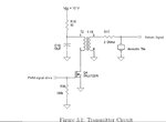
I found this circuit in a paper about the design of an acoustic altimiter.
https://www.google.co.uk/url?sa=t&r...=EgbjuhkqQnfy0tZPcvsZ9A&bvm=bv.99804247,d.d2s
I have purchased a cylindrical piezo transducer that i plan to use in place of the acoustic tile described in the paper. My cylinder has a capacitance of 6600pF and can take a voltage of up to around 1200v peak to peak. (I think I will aim for less than this at least to start with). I understand the need of a tuned reasonant circuit and think I can make a transformer that should do the job.
2 questions at the moment
1
The paper states that the circuit shown provide a little less than 500v peak to peak. How can this be? Surely a 12v supply and a transformer turns ratio of 1:19 will result in around 228v peak to peak.
2
How do I protect my micro controller from flyback voltage? Do I need to add a snubber diode somewhere? If so where and of what type?
I hope I have prepared this post properly I am not sure about the picture I tried to insert.
I will be very greatful for any assistance.
Cheers
I am new and this is my first post so please be gentle.
I am trying to make a system to transmit and recieve data underwater, or at this stage just something that will transmit an acoustic signal, a pinger, no more.

I found this circuit in a paper about the design of an acoustic altimiter.
https://www.google.co.uk/url?sa=t&r...=EgbjuhkqQnfy0tZPcvsZ9A&bvm=bv.99804247,d.d2s
I have purchased a cylindrical piezo transducer that i plan to use in place of the acoustic tile described in the paper. My cylinder has a capacitance of 6600pF and can take a voltage of up to around 1200v peak to peak. (I think I will aim for less than this at least to start with). I understand the need of a tuned reasonant circuit and think I can make a transformer that should do the job.
2 questions at the moment
1
The paper states that the circuit shown provide a little less than 500v peak to peak. How can this be? Surely a 12v supply and a transformer turns ratio of 1:19 will result in around 228v peak to peak.
2
How do I protect my micro controller from flyback voltage? Do I need to add a snubber diode somewhere? If so where and of what type?
I hope I have prepared this post properly I am not sure about the picture I tried to insert.
I will be very greatful for any assistance.
Cheers