Continue to Site

Welcome to EDAboard.com

Welcome to our site! EDAboard.com is an international Electronics Discussion Forum focused on EDA software, circuits, schematics, books, theory, papers, asic, pld, 8051, DSP, Network, RF, Analog Design, PCB, Service Manuals... and a whole lot more! To participate you need to register. Registration is free. Click here to register now.

Understanding Resistor

Status
Not open for further replies.

jptsunil

Newbie level 2
Joined
Nov 20, 2006
Messages
2
Helped
0
Reputation
0
Reaction score
0
Trophy points
1,281
Activity points
1,322
I am Absolute Begginer in Electronics
Please Help Me ............ :cry:
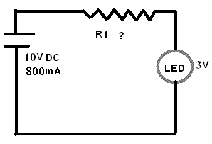
69_1164055404.GIF


Resistor of which value should be place at R1
to achieve 3v and 20mA for LED
and what will be the values of current , volatage and resistance
across each component

I am trying to understand Resistors
since last 15 days but failed badly

Please Explain in Detail
and formula to calculate this problem

i have tried on many website to understand but

- some says resistor resist current
- some says it resist voltage
- some says it resist current and drops voltage

I am in Huge Confussion if any of the above is true
then how its true and how can i calculate it
 

hi

this circuit maynot even light or draw current as the leds direction isnt shown

a diode conducts only in one direction
so its a semi conductor

power flows from the anode to the cathode so this is known as a foward bias

as you apply + to the anode current will start to flow

but an led only lights when its reverse biased
or it would just fully conduct so it sort of leeks power as light

if you have 3volts and 20ma provided the cell provides enough voltage
you only take

V=I*R to get R you transpose to
R=V/I

.:
I=0.02
V=3

3/0.02 =150R
multiply this by the cell voltage to get the needed value
so 150 ohms is the answer

so it would be
1500 or 1.5kohms

i always take shortcuts becouse i learned them first
multiply by the cell voltage is my own shortcut

the resistor is acting as a load resistor and your looking for
10v on the cell side
and 3v on the led side {but when the led runs this will draw 20ma as long as the resistors 'voltage drop' gives it 3volts


so the led can be thought of as a resistor of 150R when its running
the battery has an internal resistance also usualy very low .1R or so

so your placing in the load resistor so that the cell cant supply to much voltage
and therefore the led cant draw more current than the level of voltage allows

you need to drop 7v across this load res

im sure you see what i mean without making you do some study also

you can find many example of leds and this type
fully explained

look using google

http://www.kpsec.freeuk.com/components/led.htm

http://www.leonaudio.com.au/res_code.htm

look here for the power wheel

a must for you make a print and carry it on you
also pin it up on the wall


all these little three part equassions can be represented
as triangles

............V............
.........../ /........... divide
.......I...*...R........ multiply

if you think about a pipe that gets narrower
a resistor slows down the flow of electors {the fluid in the pipe}

so it resists the flow of voltage
therefore the current {speed of the water going past is reduced}

this causes friction in the atoms the resistor is made of
and it heats up loosing energy as heat and 'disipating' the spent voltage

this costs energy and this is the current a resistor uses to do its job
 

VSMVDD,

Are you sure what you wrote?

I think if he have 10v of vcc and wants 3v for the led the resistor should be:

R=V/I=(10v-3v)/0.02A= 350 ohms

I'ts a simple serial circuit, with two components, so he must have two diferents V values and only one current.

Please told me if I'm wrong.

By,

GuillerMo (AR)
 

    jptsunil

    Points: 2
    Helpful Answer Positive Rating
i dont use that method and your wrong anyway

your led will blow up

you need K values for led at voltage over 5v

Added after 5 minutes:

ok i stand corrected i see the mistake i made

38_1164059127.GIF
 

    jptsunil

    Points: 2
    Helpful Answer Positive Rating
Additional info for jptsunil:

A resistor is a two-terminal electrical or electronic component that resists an electric current by producing a voltage drop between its terminals in accordance with Ohm's law.

The electrical resistance is equal to the voltage drop across the resistor divided by the current through the resistor.

see, it depends on yha connection of the resistor, if series, it drops current, if parallel, it drops current. So these statements are true in their way.

Added after 4 minutes:

..
 

The original circuit can be solved with loop analysis, however it's also solvable by inspection. Here's how I would do it:

1. The battery voltage is given as 10V, and the LED voltage is given as 3V, so the voltage across the resistor is 10V - 3V = 7V.

2. The LED current is given as 20mA. All three devices are in series, so the current through the battery and resistor is also 20mA.

3. Ohm's Law says resistance equals voltage / current, so resistor = 7V / 20mA = 350 ohms.

4. For extra credit, let's calculate the power dissipated by the resistor. Power = voltage * current, so resistor power = 7V * 20mA = 0.14 watts. A common 1/4 watt resistor can safely dissipate that much power.

In a real design project, the 3V and 20mA values probably won't be given to you. Instead, you would need to read the LED data sheet to learn how much current it needs to provide the desired brightness. Then read the data sheet to learn the LED forward voltage at that current.
 

i agree with echo47. i want to add one more extra point that if led itself has an internal resistance then that also would come in series with the r1. but since it is very small and it is connected in series its usually neglected in calculations.
 

For very simple stuff at the beginning of electronics, you can collect from Engineer's Mini-notebook
**broken link removed**

nguyennam
 

jptsunil,
I can't improve on echo47's answer. However, VSMVDD's comment that an LED only lights when reverse biased is incorrect. LED's are used in the forward biased condition.
Regards,
Kral
 

**broken link removed**

Some more,
LED computation example for reference.
Hopes these help in some way.


example situation 1:
-YOur supply voltage is fixed at 12V.
-YOur LED is a typical type that requires 2V to switched on,
and can handle up to a maximum of 20mA
-A resistor to be determine, is connected in series with the LED

Voltage drop across resistor= 12V - 2V= 10V.

So now, the remaining voltage after switching on the LED is left with 10V across the unknown
resistor.

We now know the voltage across the resistor.
We know that we want to drive the LED with 20mA.
Understanding Voltage= Current x Resistance.
We can now design the correct resistor value to give us the result we want.
Resistor Value= Voltage / Current
= 10V / 20mA
= 500 ohm

Finally, you have compute the resistor value of 500ohm.
You know that by puting them in series with your LED,
and applying 12V across, you can achieve maximum brightness,
at the same time within the specification from the LED manufacturer.

example situation 2:
-YOur supply voltage is fixed at 5V.
-YOur LED is a typical type that requires 2V to switched on,
and can handle up to a maximum of 20mA
-A resistor to be determine, is connected in series with the LED

Voltage drop across resistor= 5V - 2V= 3V.

Resistor Value= Voltage / Current
= 3V / 20mA
= 150 ohm

example situation 3:
-YOur supply voltage is fixed at 1.5V.
-YOur LED is a typical type that requires 2V to switched on,
and can handle up to a maximum of 20mA
-A resistor to be determine, is connected in series with the LED

NOt possible, because the LED needs a minimum of 2V to turn itself on.
Therefore the LED will not light up at all.

example situation 4:
-YOur supply voltage is between at 5V to 12V. It can varies.
-YOur LED is a typical type that requires 2V to switched on,
and can handle up to a maximum of 20mA
-A resistor to be determine, is connected in series with the LED

Choose a situation that the highest possible current,
the LED might face.

Choose situation where supply is 12V.
Refering to example situation 1,
The resistance should be of minimum 500ohm,
to avoid over-driving the LED.

Therefore
When the supply voltage is at 12V,
the LED current consumption is 20mA (damn bright)

When the supply voltage is at 7V,
the LED current consumption is 10mA (bright)

When the supply voltage is at 5V,
the LED current consumption is 6mA (reasonable bright)

When the supply voltage is at 3V,
the LED current consumption is 2mA (may be dim)

When the supply voltage is at 1.5V,
the LED current consumption is 0mA (no light at all)
Because the LED is not switched on, and doesn't work.

End of all examples.
 

REMEMBER ONE THING........ EVERY THING IS CONTROLLED BY POWER.....P=V*I...
 

jptsunil said:
I am Absolute Begginer in Electronics
Please Help Me ............ :cry:

69_1164055404.GIF


Resistor of which value should be place at R1
to achieve 3v and 20mA for LED
and what will be the values of current , volatage and resistance
across each component

I am trying to understand Resistors
since last 15 days but failed badly

Please Explain in Detail
and formula to calculate this problem

i have tried on many website to understand but

- some says resistor resist current
- some says it resist voltage
- some says it resist current and drops voltage

I am in Huge Confussion if any of the above is true
then how its true and how can i calculate it

so 20mA(0.02A) current will flow through Resistor as it is in series...
10-3 = 7 V will appear across reistor by KVL.

R = 7/ 0.02 = 350 ohms by ohms law...
 
Last edited by a moderator:

Status
Not open for further replies.

Part and Inventory Search

Welcome to EDABoard.com

Sponsor

Back
Top