Continue to Site

Welcome to EDAboard.com

Welcome to our site! EDAboard.com is an international Electronics Discussion Forum focused on EDA software, circuits, schematics, books, theory, papers, asic, pld, 8051, DSP, Network, RF, Analog Design, PCB, Service Manuals... and a whole lot more! To participate you need to register. Registration is free. Click here to register now.

Understanding remote protocol

Status
Not open for further replies.

PA3040

Advanced Member level 3
Joined
Aug 1, 2011
Messages
883
Helped
43
Reputation
88
Reaction score
43
Trophy points
1,308
Visit site
Activity points
6,936
Dear All,

First I need to understand the remote controller protocol
Ex. Bit Patton / Length

As per attached picture I captured remoter controller signals using PICkit2 logic analyzer
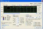
remoteeda.JPG
First I want to make sure

1. When one button pressed of remote controller, how many signals emit from the controller ( I mean single Patton or same Patton several times)

2. How we make sure that PICkit2 captured full protocol bits at ones

3. I used simple ir receiver circuit that have ir sensor and BC558 transistor for amplification and Transistor output ( collector ) connected to CH-1 of PICkit2 and I checked voltage of collector using digital meter when button presses. I observed it is reading .229mv at button pressed and non button pressed 0v
my question. is 229mv enough to drive PICkit2 CH-1 which needs 5v?

However my circuit is working and signals are measuring

Please advice
Thanks in advance
 

Attachments

  • remote.eda.bmp
    808.2 KB · Views: 63
Last edited:

That looks like Samsung IR protocol to me.

1. Depends on protocol, but for Samsung, same pattern repeated over and over with gap between messages.

2. By examination. Your pattern looks good apart from a little distortion.

3. You can only accurately measure steady signals with a voltmeter. You need an oscilloscope to see what is really happening with IR signals.

Here is a sample of Samsung codes for a modern TV:

Samsung protocol: 1/3 duty cycle 37.9khz
4.5ms mark then 4.5ms space leader
560us mark, 560us space zero
560us mark, 1.69ms space one
4 bytes, LSB first
byte1 custom byte, byte2 repeat of byte 1, byte 3 data, byte 4 inverted byte3
end bit of '1'
---------------------------------------------------------------------------------------------

Samsung TV remote AA59-00581A
measured 37.0 kHz

07(00) ?
07 01 source
07 02 on/off
07(03) sleep timer
07 04 1
07 05 2
07 06 3
07 07 vol+
07 08 4
07 09 5
07 0A 6
07 0b vol-
07 0C 7
07 0D 8
07 0E 9
07 0f mute
07 10 ch-
07 11 0
07 12 ch+
07 13 previous ch
07 14 B green
07 15 C yellow
07 16 D blue
07 1a menu
07(1b) tv input
07(1d) ?
07 1f info
07(20) pip
07(23) ?
07 25 ad/subt
07(27) ?
07(28) picture mode
07(2b) sound mode
07 2c ttx/mix
07 2d exit
07(32) ?
07(33) ?
07(36) ?
07(3b) ?
07(3c) ?
07(3d) ?
07 3e picture size
07 3f support
07(40) ?
07(43) tv input select
07(44) ?
07 45 rewind
07 46 stop
07 47 play
07 48 fast forward
07 49 record
07 4a pause
07 4b tools
07(4d) Universal Remote setup !!! ******
07 4f guide
07(50) ?
07(51) ?
07(52) audio language
07 58 return
07 60 up arrow
07 61 down arrow
07 62 right arrow
07 65 left arrow
07(66) twitter
07 68 enter
07 6b ch list
07 6c A red
07(6e) ?
07 73 search
07(76) ?
07(77) energy saving
07 79 smart
07(7A) VCR
07(7b) cable
07(7d) TV
07(7e) DVD
07(7f) STB
07(84) EXT
07(86) component
07(87) clock set
07 8b HDMI
07(8c) smart hub social TV
07(8d) ?
07(8f) ?
07(93) smart hub
07(98) off
07 9f 3d
07(bd) picture mode dynamic
07(be) HDMI2
07(c0) ?
07(c2) HDMI3
07(c5) HDMI4 if fitted (no HDMI4 on my TV)
07 c6 family story
07(c8) ?
07(c9) ?
07(ca) ?
07(cc) ?
07(d1) Bluetooth Pairing
07(de) picture mode movie
07(df) picture mode standard
07(e3) pictire size 4:3
07(e4) picture sixe 16:9
07(e9) HDMI1
07(ec) AV input select

brackets show discreet input codes, not on standard remote
 
  • Like
Reactions: PA3040

    PA3040

    Points: 2
    Helpful Answer Positive Rating
Dear Hexreader Thank you so much for detailed reply


This is "INNOVEX" LCD TV remote controller, I think Samsung compatible, not sure

4.5ms mark then 4.5ms space leader

I think you are pointing out in the above "mark" and "leader" that I pointed out my picture Letter "B" and "C". Am I correct?

Could you please advice what I point out letter "A" in my picture

X-Y = 9.2ms what is meaning ( Please see being A)
108.70 Hz. Is this frequency of the protocol?
edaremote1.JPG

Please advice
Thanks in advance
 

I think you are pointing out in the above "mark" and "leader" that I pointed out my picture Letter "B" and "C". Am I correct?
Absolutely correct. The 4.5ms high (mark) followed by 4.5ms low (space) is the leader

Could you please advice what I point out letter "A" in my picture
This is the leader time of 9ms.

X-Y = 9.2ms what is meaning ( Please see being A)
This is the leader time of 9ms

108.70 Hz. Is this frequency of the protocol?
No, this frequency has no meaning. A protocol does not have a frequency. There will be a carrier frequency of typically 36kHz, 38kHz or 40kHz, but you will not see this at the receiver, as the carrier is removed by the receiver chip.


My favourite site for explaining domestic IR is here: https://www.sbprojects.com/knowledge/ir/index.php , but sadly it does not include Samsung protocol.
 
Last edited:
  • Like
Reactions: PA3040

    PA3040

    Points: 2
    Helpful Answer Positive Rating
Dear Thanks again and again for valuable details

My favourite site for explaining domestic IR is here: https://www.sbprojects.com/knowledge/ir/index.php , but sadly it does not include Samsung protocol.

This is very useful information's to me

It would be much appreciated, would you please guide me how may I write the program capture leader

First I need to study to capture only leader, that will help to me than studding whole protocol,

Let's we assume that the signals IN to RA0 of PIC 16f877a MCU

Using Assembly

I can Check

BTFSS PORTA,0
GOTO $-1

Please advice other step if above steps are correct

Please help
Thanks in advance
 

Here is a snippet of code with 3 handy subroutines from a project to read NEC protocol using PIC12F683:

Code:
;time how long a low pulse is - low is a mark
timeirlow
	clrf	lowtime
ltloop
	incf	lowtime,f
	btfsc	STATUS,Z
	decf	lowtime,f	;don't allow increment past 255
	call	slowir		;limit sample rate
	btfss	irin
	goto	ltloop
	movfw	lowtime
	return

;time how long a high pulse is - high is a space
timeirhigh
	clrf	hightime
htloop
	incf	hightime,f
	btfsc	STATUS,Z
	decf	hightime,f	;don't allow increment past 255
	call	slowir		;limit sample rate
	btfsc	irin
	goto	htloop
	movfw	hightime
	return

;limit sample rate
slowir
	movlw	d'20'
	movwf	timer1
sirloop
	decf	timer1,f
	btfss	STATUS,Z
	goto	sirloop
	return
Attached is the complete ASM source file, which is probably too much to take example from, but you might need to see the definitions for the above subroutines.

View attachment nec2serial8.rar
 
  • Like
Reactions: PA3040

    PA3040

    Points: 2
    Helpful Answer Positive Rating
Dear Hexreader

Thanks for reply

I think you don't angry with me if I ask

The above code is whole protocol reading code or only for "mark" and "space"

If it is whole code, still I can't understand ( Sorry )

can you please give me the code belonged to "mark" and "space" capture
Then I will be understand the logic then understand whole protocol

Thanks in advance
 

The code in the code box is only part of the code that you need to make up a PIC program.
Note that for my circuit, mark is low and space is high. You hardware is different and mark is high while space is low.

There is an attachment with a much larger, but complete project. It is for PIC12F683, so not suitable for your PIC16

I cannot provide you with custom code as MPLAB does not work on my current computer.

There are Gooligum tutorials that can teach you MPLAB assembly programming - just Google for "Gooligum"
 
  • Like
Reactions: PA3040

    PA3040

    Points: 2
    Helpful Answer Positive Rating
Dear Hexreader,

Code:
;limit sample rate
slowir
	movlw	d'20'
	movwf	timer1
sirloop
	decf	timer1,f
	btfss	STATUS,Z
	goto	sirloop
	return

I think above code count the time of "mark" Am I correct?
Could you please explain important of d'20'

Please help
 
Last edited:

Dear Hexreader,

Code:
;limit sample rate
slowir
	movlw	d'20'
	movwf	timer1
sirloop
	decf	timer1,f
	btfss	STATUS,Z
	goto	sirloop
	return

I think above code count the time of "mark" Am I correct?
Could you please explain important of d'20'

Please help
No, this is a simple delay subroutine. d'20' is decimal number 20 and sets the number of loops in the delay routine and thus adjusts the delay.

Go through the Gooligum tutorials here: **broken link removed** and you will learn how to program delays and many other useful things.

The free lessons are enough to teach you the basics.
 
Last edited:

Status
Not open for further replies.

Similar threads

Part and Inventory Search

Welcome to EDABoard.com

Sponsor

Back
Top