Continue to Site

Welcome to EDAboard.com

Welcome to our site! EDAboard.com is an international Electronics Discussion Forum focused on EDA software, circuits, schematics, books, theory, papers, asic, pld, 8051, DSP, Network, RF, Analog Design, PCB, Service Manuals... and a whole lot more! To participate you need to register. Registration is free. Click here to register now.

[SOLVED] Unbalanced input (50ohm) and Balanced Output (150ohm)

Status
Not open for further replies.

amirke

Member level 5
Joined
Mar 31, 2012
Messages
92
Helped
0
Reputation
0
Reaction score
0
Trophy points
1,286
Activity points
1,927
Hello,

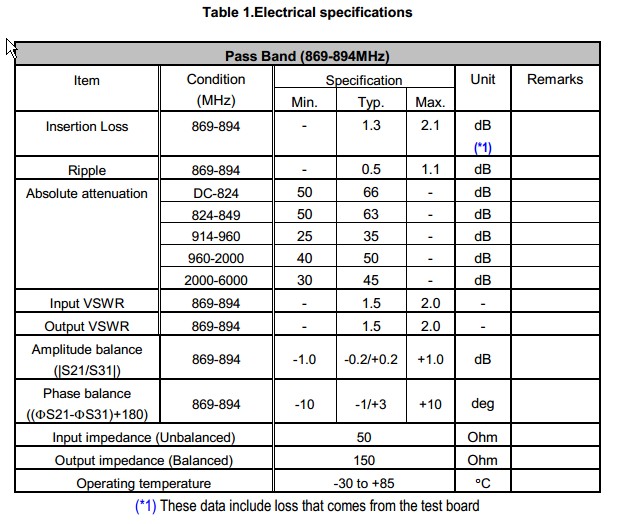
I have this SAW filter: **broken link removed**

It says that it has Unbalanced input (50ohm) and Balanced Output (150ohm).
In the Evaluation Circuit (page 2 in the datasheet) of this filter there is an inductor of 15nH.

Previous stage is LNA and next stage is PA.

Assuming that LNA and PA have balanced Inputs and Outputs, What do I need to do in this filter ?

and another question : Why is the input balanced to 50E and the output to 150E ?

Thanks
 

Assuming that LNA and PA have balanced Inputs and Outputs, What do I need to do in this filter ?
You would want to connect a LC balun+matching circuit between the LNA and the filter.
and another question : Why is the input balanced to 50E and the output to 150E ?
Why some people are 6 feet high? Probably the filter has been designed for a particular application. If you don't like it, look out for a different one. Or live with it.
 

You would want to connect a LC balun+matching circuit between the LNA and the filter.

So if the LNA output is 50E, Then I need to connect matching circuit to 50E before the filter ?

And if the output is balanced to 150E then I need to wotk with PA input balanced to 150E ? (and the trace as well?)

Why in the datasheet they connected an inductor of 15nH in Filter's output ?

Thanks
 

Unfortunately, the datasheet is partly unclear. The output impedance specification in the table would be normally read as an inductive output impedance. The evaluation circuit suggests in contrast, that the output impedance of the filter is capacitive and should be compensated with an inductor. The Smith diagram shows an almost real output impedance, but misses a reference impedance specification.

Preferably, you should ask for a manufacturer clarification or measure the parameters yourself.
 
  • Like
Reactions: amirke

    amirke

    Points: 2
    Helpful Answer Positive Rating
Thanks,

I asked the manufactur 3 days ago. Waiting for an answer.

So, Basically, When a datasheet as this one (same vendor, different filter) : **broken link removed**
Points that an input is "unbalanced input" and adds "50E", what does that mean ?
If it is unbalanced, Then I can match it as I wish. Why it point 50E ?

And when in the Datasheet is written "Balanced Output (150ohm)" that means that I can connect any device that has balanced input of 150E with no matching part by me, correct ?
 

Impedances should be matched both for single ended ("unbalanced") and differential ("balanced") ports.
 

Yes, I understand it should be matched.

Now I understand that single ended = unbalanced and differential = balanced , correct ?

But I need more clarification : if the datasheet says that


Input impedance (Unbalanced) 50 Ohm
Output impedance (Balanced) 150 Ohm

Then It is best for working with devices that has 150E input impedance and 50 output impedance ?

Thanks
 

Then It is best for working with devices that has 150E input impedance and 50 output impedance ?
Yes. In this case, no impedance matching circuit is required. Otherwise, usual LC matching circuits would be utilized.
 
  • Like
Reactions: amirke

    amirke

    Points: 2
    Helpful Answer Positive Rating
Status
Not open for further replies.

Part and Inventory Search

Welcome to EDABoard.com

Sponsor

Back
Top