arbj2
Full Member level 3
Hi,
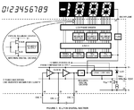
I am trying to hack a digital multimeter (MAS730) to connect the digit pins to a micro-controller. The schematic is attached.
I am unable to locate the ground reference for the mcu. The datasheet lists pin 28 (BP/GND) as the ground ref for the AME7107 decoder IC. However this does not seem to be connected anywhere in the circuit
I would like the mcu to detect high or low on each of the digits pins. Using this I can determine the digits being displayed.
From the schematic I notice that the BP pin is not connected to the ground anywhere. But as the mcu will be powered from the same power supply as the meter, how can I derive a suitable ground for the micro-controller ?
One solution would be to connect the mcu across the +V (pin 8) and the BP pin of the AME7107. But the IC works on 2.6V DC, also with an oscilloscope across these pins I noticed that the supply to the AME7107 chip is pulsing, Is this how it is supposed to work ??
The schematic and the datasheet is given below.
View attachment ame7106.pdf
thanks
a
I am trying to hack a digital multimeter (MAS730) to connect the digit pins to a micro-controller. The schematic is attached.
I am unable to locate the ground reference for the mcu. The datasheet lists pin 28 (BP/GND) as the ground ref for the AME7107 decoder IC. However this does not seem to be connected anywhere in the circuit
I would like the mcu to detect high or low on each of the digits pins. Using this I can determine the digits being displayed.
From the schematic I notice that the BP pin is not connected to the ground anywhere. But as the mcu will be powered from the same power supply as the meter, how can I derive a suitable ground for the micro-controller ?
One solution would be to connect the mcu across the +V (pin 8) and the BP pin of the AME7107. But the IC works on 2.6V DC, also with an oscilloscope across these pins I noticed that the supply to the AME7107 chip is pulsing, Is this how it is supposed to work ??
The schematic and the datasheet is given below.
View attachment ame7106.pdf

thanks
a
