gopalgj
Newbie level 4

- Joined
- Sep 4, 2010
- Messages
- 5
- Helped
- 0
- Reputation
- 0
- Reaction score
- 0
- Trophy points
- 1,281
- Activity points
- 1,319
Hi Guys,
I need help to understand the inner working of US distance measurement sensor.
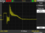
I was very amazed with the quality of the output from the "HC-SR04" sensor. So, I started digging into the circuit. There isn't any schematic of the board and I started by looking at the waveform on the Transmitter transducer pins. I'm struck on the first step. This is the screenshot of the Oscilloscope. .
.
The MAX3232 drives 8-cycle burst (-5v to 5v) of 40KHz which is clear. But, why is it applying a DC of 10v for roughly about 10 cycles (250us)? I was expecting the ringing/damping waveform to have smaller amplitude. But, it seems like the ringing is more pronounced with the driver removed. It takes about 1ms to settle down which is in line with the spec.
Thanks,
Gopal
I need help to understand the inner working of US distance measurement sensor.
I was very amazed with the quality of the output from the "HC-SR04" sensor. So, I started digging into the circuit. There isn't any schematic of the board and I started by looking at the waveform on the Transmitter transducer pins. I'm struck on the first step. This is the screenshot of the Oscilloscope.
 .
.The MAX3232 drives 8-cycle burst (-5v to 5v) of 40KHz which is clear. But, why is it applying a DC of 10v for roughly about 10 cycles (250us)? I was expecting the ringing/damping waveform to have smaller amplitude. But, it seems like the ringing is more pronounced with the driver removed. It takes about 1ms to settle down which is in line with the spec.
Thanks,
Gopal
