Continue to Site

Welcome to EDAboard.com

Welcome to our site! EDAboard.com is an international Electronics Discussion Forum focused on EDA software, circuits, schematics, books, theory, papers, asic, pld, 8051, DSP, Network, RF, Analog Design, PCB, Service Manuals... and a whole lot more! To participate you need to register. Registration is free. Click here to register now.

ULN2803 Doesn't have Vcc Pin, How I'm suppose to use it?

Status
Not open for further replies.

umery2k75

Advanced Member level 1
Joined
Apr 19, 2006
Messages
434
Helped
41
Reputation
80
Reaction score
15
Trophy points
1,298
Location
Pakistan
Activity points
5,748
using uln2803

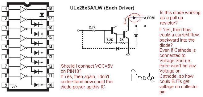
I think I must connect Vcc=5 Volt on the Common pin, that is Pin number 10.I don't understand the concept of diode as shown in the diagram. It seems like as if it's working like a pull up resistor. I also don't understand the other two diodes drawn in a dashed lines (- - - - -). By studying various other examples on ULN2803, I hope to learn how this IC work in a few more time. Most importantly, I want to understand the logic behind it.
 

how to use uln2803

Pin 10 is often connected to the supply, but not as a pull-up. If the load is inductive, the terminal voltage will rise when it is switched off. The diodes provide a path for the inductor's current, while clamping the output to the voltage at pin 10, plus the forward voltage of the diode.
The dashed diodes are to prevent the driver's input from being taken much below 0V, usually to prevent damage.
 

uln2803 example


I'm sorry, I couldn't upload the diagram. This is it. Even in Some circuit schematics I have seen that people don't even use the PIN 10. Still they are using it as a driver for high current source.
Check this PDF file.
 

how to use uln2803a

I know the concept of open collector as well as of the open drain. So Is that diode a kind of active pull up, as we can have another transistor in it, which makes up a active pull up.Similarly in a fashion like Push Pull configuration. If I talk about passive pull up then I have resistor, so Is this some kind of clamping or something related with it? Do you agree the diode is working as a passive pull up?
 

pin diagram of uln2803

Hi,
No, the diode is not an active pull up, as already mentioned above, it is voltage clamping diode to clamp the inductive 'kick-back' voltage when an inductive load like relay coils connected across the collector and Vcc are being switched off. The standard connection is to connect the common pin to power supply and connect the load across power supply and the transistor collector. When the transistor is switched on, the current flows through the load, to the collector-emitter and ground. When it is switched off, if the load is inductive, like coils, a reverse voltage is generated across the coil, which will add to the power supply voltage and will raise the collector-emitter voltage of the transistor momentarily and if this voltage exeeds the VCEO limit of the transistor, it can break down. At this time the diode connected as shown in the diagram, across the coil, conducts and limits the reverse kick-back voltage to one diode drop and the collector-emitter voltage gets limitted to Vcc+ one diode drop, thus protecting the transistor.

One disadvantage of a simple diode clamping like this is that the conducting diode keeps the coil energised for a little longer period, thus increasing the release time of the relay contacts. If this is critical, you can connect a diode in series with a zener diode having voltage rating equal to Vcc, thus increasing the clamping voltage to Vcc + one dide drop and limiting collector emitter volatge to about twice the value of Vcc.

The other two diodes with their anodes conncted to ground is to limit any negative spikes picked up to a safe limit of -(one diode drop).

Regards,
Laktronics
 

    umery2k75

    Points: 2
    Helpful Answer Positive Rating
uln2803 pin configuration

hi,
If you understand the concept of open collector you know must where the supply voltage is coming from, you are using the device as laktronics said to switch a relay etc, one end of the relay coil is connected to V+ (also connected to the common pin 18) the other to an output of the ULN2803 which will pull the output to its ground point when the input is energised as the drivers are inverting.
Regards,
Bob.
 

using a uln2803

I put decoupling capacitors in between Vcc and Gnd for other ICs. Is there need for decoupling capacitor in this IC ULN2803. I think NOT. I think so, because I believe this IC is not more than an array of transistor, as we don't decouple the transistor, so we don't do that in this IC too. Even It's open collector. So we can't use decoupling capacitor in open drain, collector configuration.
Is decoupling capacitors always used across Vcc or Gnd, or it could be used in other sense too?
 

uln2803 uses

Hi,
It depends on what you are driving, if you are driving relays it might be advisable because it would minimise false triggering if there is any overshoot pulse from the relay coil inductance remaining that the flyback diode does not block. If you have the space for it on your board it is always wise to include it rather than not as its presence will never be a bad thing. It is not necessrary to put one adjacent to every device like you would normally do with a memory etc but the inclusion of one that is rasonably close to the device is normally recommended. Remember the inputs are like a ttl schmitt gate not a simple transistor base.
Regards,
Bob.
 

uln2803 common

uln is work like a not ic for example if we use 5v for input we'll have 0 in output and it is so gooood for more current needing :D
 

uln2803 how to use

hello..

You should read the datasheet. there's content how to use on the applications.

regards.
 

ic uln2803

we have a small PLC controller with a switching power supply and the ULN 2803 that controls devices either at 5 volts or using the wall adapter power supply.

check it out.

www.thesiliconhorizon.com
 

Status
Not open for further replies.

Part and Inventory Search

Welcome to EDABoard.com

Sponsor

Back
Top