Continue to Site
Follow along with the video below to see how to install our site as a web app on your home screen.
Note: This feature may not be available in some browsers.
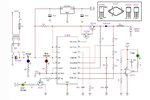
Hi tpetar, I know this data sheets. Did you have schematic for UC3906 for Battery Charger 12V with output current 30A?
Hi kyrietec, I try to changing the PNP and NPN transistor but output only 3 -5A. For transformer 50 A. Did you have schematic or sample circuit?Yes.If and only if the cct.is upgrade by changing the pnp,npn transistor at pin16 diode and the resistor look at the cct
- - - Updated - - -
And the transformer also upgrade
Output from transformer 18VWhat is output voltage of the transformer?
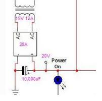
What is the voltage reading at this point (20V) in the actual circuit, while charging.
Yes i use 12V. If I use 15V,I was afraid my battery quickly broken.So that's the problem. This voltage is not sufficient for this cicuit. There are many points where voltage is dropped before reaching the battery terminals. There is sense resistor, pass transistor and a rectifier diode, all dropping voltages. I think you are using 12V, not 15V transformer as shown in schematics.
AC voltage, when recified to DC by full bridge diodes and filtered by capacitor, DC increases 1,4 times AC. 15 x 1.4 = 21V DC. Why you are not getting that voltages at least at no charging state.
Frankly your cicuit is no good for use at that current. If it is dropping 5-6V at 30A, you have to dissipate 150-200 watts as heat.
Yes, I need control charging, when current reach certain level it will stop.What you need is it circuit that can control charging , when voltage reach certain level it will stop
- - - Updated - - -
What you need is it circuit that can control charging , when voltage reach certain level it will stop
Hi Kyrietec, in your circuit, what are you using? Current or voltage sensor?Use any of this circuit .View attachment 92249
Hi Kyrietec, in your circuit, what are you using? Current or voltage sensor?
Many thanks for your explanation.Circuit 1.Reset the voltage through variable resistor.If the system reset at 13.8v when the battery reach 13.8v the relay will switch on by switching off your transformer input,when the battery voltage drops the relay will switch off the start charging. Circuit 2.Connect relay the same way in cct 1.Retset the voltage through variable resistor.Inverting input is regulated voltage 5.6v,noninverting input is unregulated voltage the input depend on battery voltage .when noninverting input voltage is >or=inverting input the relay will switch on.if battery drops the relay will switch off.Both cct. switching on relay depend on voltage you reset it .Your charging current depend on your transformer.
You can use triac to control the charging current.Many thanks for your explanation.
But i need charging with current controller. Your circuit can be use, but can not detect the battery is good or faulty?