Continue to Site
Follow along with the video below to see how to install our site as a web app on your home screen.
Note: This feature may not be available in some browsers.
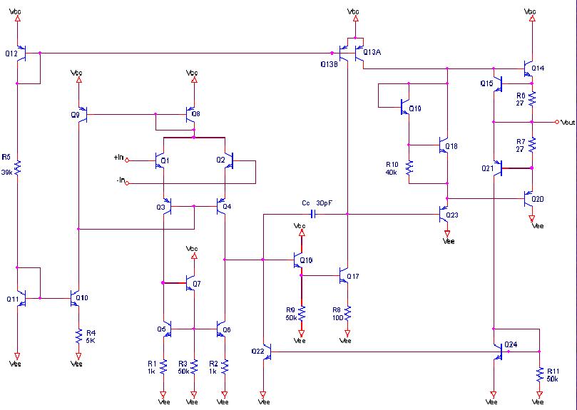
Simply assume two transistors.I found this symbol in another ua741 op amp schematic but unfortunately i couldn't find this symbol in PSpice.
Yes, connect base and emitter of both.'ll need to use two bjt to represent that dual collector bjt?
It should basically work. For a realistic modelling, you have to understand the constraints of the 70th planar technology used with uA741 and choose correct transistor parameters, particularly for lateral and substrate pnp. Gray/Meyer Analysis and Design e.g. has all necessary information, you'll possibly also find transistor level models in literature.I use transistor level op amp of ua741 instead of the op amp ua741 available in PSpice so that i can get the changes in frequency response when i vary the temperature. That's my main reason and i really hope it works.
")
Audioguru said:The lousy old 741 opamp is more than 40 years old. It should be buried.
741 works too ;-)