Welcome to our site! EDAboard.com is an international Electronics Discussion Forum focused on EDA software, circuits, schematics, books, theory, papers, asic, pld, 8051, DSP, Network, RF, Analog Design, PCB, Service Manuals... and a whole lot more! To participate you need to register. Registration is free. Click here to register now.
Diode impedance depends on the circuit where it is used.
If used as a detector, it depends on input RF power. If used in a mixer, then it depends on the LO input power, and also if the mixer is balanced, etc.
Check textbooks on detectors and mixers for details.
Diode impedance depends on the circuit where it is used.
If used as a detector, it depends on input RF power. If used in a mixer, then it depends on the LO input power, and also if the mixer is balanced, etc.
Check textbooks on detectors and mixers for details.
In my circuit it is used as a doubler rectifier (2 diodes).
I would like to incluse an input attenuator pad 50R in to whatever diode impedance out, that is why I am asking.
The "impedance" of a diode is the sum of bulk resistance and differential resistance rd = dV/dI which is current dependent according to the exponential diode characteristic.
You can derive both numbers from the datasheet forward characteristic. OA 90 bulk resistance range is 25 - 100 ohm according to datasheet, typically 50 ohm.
So it is roughly already matched or I have to add the Rd to this value as well?
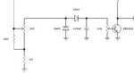
The circuit I consider is this. It uses a aproximately 50R input attenuator to the diodes. The diodes are used as charge pumps, so I think impedance matching would not be too critical on HF anyway.
In this app, Rd is varied so I think I cannot consider constant impedance...
So it is roughly already matched or I have to add the Rd to this value as well?
The circuit I consider is this. It uses a aproximately 50R input attenuator to the diodes. The diodes are used as charge pumps, so I think impedance matching would not be too critical on HF anyway.
In this app, Rd is varied so I think I cannot consider constant impedance...
For such application I am not sure what input power is. I used GaAs Schottky diode pairs as doublers, and under 17-18 dBm input the input impedance was close to 50 Ohms, also over a wide band.
The best way to know is to use a reflectometer and measure S11 as a function of input power. Use such level that gives the best ouput, with luck this may coincide with a good match.
This site uses cookies to help personalise content, tailor your experience and to keep you logged in if you register.
By continuing to use this site, you are consenting to our use of cookies.