Continue to Site

Welcome to EDAboard.com

Welcome to our site! EDAboard.com is an international Electronics Discussion Forum focused on EDA software, circuits, schematics, books, theory, papers, asic, pld, 8051, DSP, Network, RF, Analog Design, PCB, Service Manuals... and a whole lot more! To participate you need to register. Registration is free. Click here to register now.

type of transistor biasing?......

Status
Not open for further replies.

karthickb3e

Advanced Member level 4
Joined
Dec 13, 2010
Messages
101
Helped
3
Reputation
6
Reaction score
3
Trophy points
1,298
Location
INDIA
Activity points
1,883
hi every one,,..
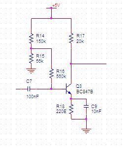
i have doubt about the biasing of the following circuit.... please help regard this...
i understood the use of R14 and R15 (voltage divider bias)..
then what is the need of using the resistor R16...


https://obrazki.elektroda.pl/48_1323506886.jpg


48_1323506886.jpg
 
Last edited:

Yes, the circuit as shown could use different values for R14/15 and omit R16. You would want to keep the total resistance as viewn from the base and resistance ratio. A possible purpose of three resistor circuit reveals when additional filtering is intended, adding a capacitor parallel to R15.
 

as said by FvM , one choice is with proper R14 and R15 alone without R16.

but when R16 is included you will have a different ac signal equalant behaviour.
signal from C7 will go to base and due to highvalued R16 it be seen as opencircuit.
 

Perhaps it's helpful to add some general aspects related to BJT biasing:
* In general, there are two basic concepts: (a) bias current injection (using a very large resistor) or (b) bias voltage injection (using a relatively low-resistive voltage divider).
* Besides the signal input resistance, which is of course different in both cases, the choice depends on the desired dc stabilisation principle.
* case (a):If voltage controlled current feedback is to be realized (with a driving voltage derived from the collector path)
* case (b): If current controlled voltage feedback is to be realized (with an additional emitter resistance).This works best for a low-resistive divider at the base, however, due to current consumption aspects and input impedance requirements a trade-off often is made.
* Of course, also a combination of both can be envisaged (as in the shown circuit).
 
Last edited:
LvW reminded me, that my previous comments ignored reasonable circuit operation, because I restricted myself to answering the raised question only.

Applying the criteria explained by LvW to the said circuit, you realize, that's a rather bad design. Voltage divider and capacitively bypassed emitter resistor suggests case (b), current controlled voltage feedback. But unfortunately the emitter resistor value is much too low a achieve a noticeable feedback (a few 10 mV voltage drop across the resistor). In return, the voltage divider has a too high impedance of about 600k to source a constant reference voltage. Effectively, the circuit stabilization effect isn't anything better than a single resistor between Vcc and base, omitting the emitter resistor. This circuit works only, if the resistor value is matched to the transistor current gain. This circuit, base current injection without feedback is the second worse biasing method, the worst would be voltage injection without feedback.

To change the circuit operation to more stable bias, you would either apply said method (a) by connecting the feedback resistor to the collector instead to a voltage divider, or method (b) by increasing R18 and omitting R16, keeping the lower divider resistance level.
 
  • Like
Reactions: LvW

    LvW

    Points: 2
    Helpful Answer Positive Rating
Yes, I totally agree to FvM's explanations. The concept with a (rather small) emitter resistance together with dc bias current injection is not very effective.
 

Voltage Divider Bias

The purpose of Voltage Divider Bias is to provide a stable DC voltage at the base of the transistor regardless of the beta of the transistor.
The disadvantage of Voltage Divider Bias stems from the need to make the voltage divider stiff. A stiff voltage divider will reduce the input impedance of the amplifier.
This essentially wastes the efficiency of the amplifier to provide voltage gain or current gain as compared to say base bias.
It would appear to me that this design is an attempt to swamp out the effects of the Voltage Divider on the AC input impedance while maintaining the stable base voltage reference of the voltage divider.
One thing I'm not clear on is the value of R18...is that 220 ohm? What is the E?
If R18 is 220 ohm then the incredibly high ratio of R16/R18 will create a large voltage drop across R16 and effectively destroy its own purpose.
Also, the incredibly high ratio of R17/R18 means that Ve can be no more than 0.05V because the transistor will saturate.
 

The presence of an emitter resistor makes it necessary to increase the voltage at the bias higher than 0.6 V.

If bias voltage is too low then the transistor will not turn on.

In practice it is easiest to use a potentiometer. Adjust bias current so it yields proper operation.

Eventually you can substitute a 2-resistor divider if desired (because pots are known to get scratchy).

80_1323559358.gif
 

Status
Not open for further replies.

Similar threads

Part and Inventory Search

Welcome to EDABoard.com

Sponsor

Back
Top