Continue to Site

Welcome to EDAboard.com

Welcome to our site! EDAboard.com is an international Electronics Discussion Forum focused on EDA software, circuits, schematics, books, theory, papers, asic, pld, 8051, DSP, Network, RF, Analog Design, PCB, Service Manuals... and a whole lot more! To participate you need to register. Registration is free. Click here to register now.

Two Transistor Forward best driven like "half a Full Bridge"?

Status
Not open for further replies.
T

treez

Guest
Hi,

Would you agree that the Two Transistor Forward is best driven like a Full Bridge with 2 diagonal FETs replaced by just diodes? (ie like “half full bridge”)

Then you can use a Bootstrap high side driver without suffering a delay before the Bootstrap capacitor gets charged up. If not done like “half a Full Bridge”, then the delay in charging the bootstrap capacitor means that the error amplifier output gets railed high at startup and then one finds oneself getting startup overcurrents. Would you agree?

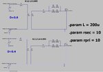
Comparison attached (pdfs and LTspice sims) of Two Transistor Forwards with Bootstrap drivers , but one in “half full bridge” mode, the other in “plain bootstrap” mode.

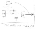
“Plain Bootstrap” is clearly inferior with regards to delayed Bootstrap cap charging at startup, as well as poor light load performance. (since there’s little or no refresh of the bootstrap cap)

Would you agree?
 

Attachments

  • 2TF _Full bridge driver.pdf
    31.7 KB · Views: 52
  • 2TF _Full bridge driver.txt
    9.4 KB · Views: 37
  • 2TF Bootstrap driver.pdf
    30.7 KB · Views: 55
  • 2TF Bootstrap driver.txt
    9.9 KB · Views: 41

if you are that worried about it why not turn on the lower fet for 50uS at cold start ( i.e. disable the high side drive for 50uS ) to charge the high side fet's bootstrap ckt ( via the Tx pri ) and then allow normal gate drive after the 50uS .... - or use a GD Tx to drive both fets ...

The 2 diode / 2 fet fwd converter is quite elegant and doesn't benefit too greatly from the extra fet you have drawn in ...
 
  • Like
Reactions: treez

    T

    Points: 2
    Helpful Answer Positive Rating
if you are that worried about it why not turn on the lower fet for 50uS at cold start ( i.e. disable the high side drive for 50uS ) to charge the high side fet's bootstrap ckt ( via the Tx pri ) and then allow normal gate drive after the 50uS .... - or use a GD Tx to drive both fets ...
Thanks, yes , i see your point, though from that point we wondered about light load or no load, and how the bootstrap cap at that time is not getting well refreshed.......whereas with the full bridge driver method it gets a more certain refresh charge.

or use a GD Tx to drive both fets ..

This is one of the things we dont like about Transformer gate drives....
 
Last edited by a moderator:

there are much better and straightforward ways to employ a good GD transformer for 2 sw fwd or full bridge - we use a single GD TX for 3kW ... full bridge
 

    T

    Points: 2
    Helpful Answer Positive Rating
Thanks, yes i think you described previously, it was a PSFB and then the gate drives are always 50%/50%....which makes the gate drive very straightforward, and there's no need for the "dc restore" type of gate drive thats needed in a 2TFC..

The trouble with "non dc restore" type gate drives, as you know, when not constant duty cycle, then the drive voltage varies with the duty cycle.
 

    thomasx

    Points: 2
    Helpful Answer Positive Rating
not if you drive it correctly - we have 0 - 49.5% pwm on 4 o/p's of a GD Tx, driven from a UC3856, we like to use the +15 / -7v5 we get from this to give more gate rise immunity - the magnitudes do not change with PWM ....
 
Thanks, yes, as the attached shows, a “push pull gate drive, with no series caps”, does maintain the drive voltage regardless of duty cycle. Though as you know, the Gate drive transformer needs all the customisations necessary to minimise leakage inductance, because a “turn-off PNP” type circuit cannot be used, as it can with the “DC restore gate drive”

Attached if you wish: LTspice and pdf of bipolar, push pull gate drive
 

Attachments

  • Bipolar gate drive_no caps.jpg
    Bipolar gate drive_no caps.jpg
    115 KB · Views: 50
  • Bipolar gate drive_no series caps.txt
    4.3 KB · Views: 51

The good thing about the two transistor forward when driven with “DC restore type Gate drive transformer”, is that you can drive the bottom fet directly…and then drive the top fet from a DC restored gate drive transformer (GDT). This means that you get fast turn off of the top fet and bottom fet (because the top fet has a PNP turn off circuit)…but also, you get slow turn ON of the top fet due to the GDT leakage inductance………however, one gets round this be delaying the turn-ON of the bottom FET…then the top fet turns on first into no current…so problem solved…this is why we like the “DC restore type” gate drive for Two Tran fwd.

Here is the circuit, as you know, to delay the turn ON of the bottom fet (attached)

As you know, if you dont do it like this, then one has to do the "custom special low leakage inductance" gate drive transformer...as described in the attached document.........i think unfortunatly a dedicated Quality engineer would be needed on this alone.
 

Attachments

  • Delayed turn ON of bottom fet in 2tfc.jpg
    Delayed turn ON of bottom fet in 2tfc.jpg
    49.4 KB · Views: 149
  • Tips for making a good Gate Drive Transformer.zip
    7.7 KB · Views: 103

Status
Not open for further replies.

Similar threads

Part and Inventory Search

Welcome to EDABoard.com

Sponsor

Back
Top