Continue to Site

Welcome to EDAboard.com

Welcome to our site! EDAboard.com is an international Electronics Discussion Forum focused on EDA software, circuits, schematics, books, theory, papers, asic, pld, 8051, DSP, Network, RF, Analog Design, PCB, Service Manuals... and a whole lot more! To participate you need to register. Registration is free. Click here to register now.

TV modulator/amplifier connection

Status
Not open for further replies.

neazoi

Advanced Member level 6
Joined
Jan 5, 2008
Messages
4,157
Helped
13
Reputation
26
Reaction score
15
Trophy points
1,318
Location
Greece
www.microwave.gr
Activity points
37,198
Hello I would like to combine these two circuits to form a small transfmitter.
The output of the modulator is through a 2.7pf and the input of the amplifier is through a 22pf.
Should i remove one of the two capacitors and couple the two circuits with just one capacitor?
Which one should I remove, the 22pF or the 2.7pF
I guess for stability reasons and for lightly loading the modulator, I should keep just the 2.7pF?
 

Attachments

  • Tvtx1.gif
    Tvtx1.gif
    26.7 KB · Views: 87

I would keep the 2.7 PF, a 22PF in series will not materially change its effective value.
Frank

Thanks,
I was also wondering if I can replace the BFY90 on the amplifier section, with 2sc9018.
By looking at the datasheets they have similar characteristics. Can I do it, or what changes would be needed to replace them?
 

Attachments

  • 2sc9018.pdf
    77.3 KB · Views: 79
  • bfy90.pdf
    161.6 KB · Views: 92

Thanks,
I was also wondering if I can replace the BFY90 on the amplifier section, with 2sc9018.
By looking at the datasheets they have similar characteristics. Can I do it, or what changes would be needed to replace them?


Transistors look replacable,no issue..
2.7pF has been used to drive an antenna to prevent the oscillator stopping.Because if oscillator is loaded with relatively low impedance it may stop to oscillation.
However, the capacitor at the input of the amlifier (22pF) is used because it's been supposed that a 50Ohm(75Ohm) generator will be used.That's why neither 2.7pF nor 22pF may not be optimum value.I reecommend you to choose an optimum capacitor value for this coupling by cut-and-try method.
2.7pF may be too small to drive your amplifier so output level can not reach to the wanted level.In the other hand, 22pF may be too large to eventually to stop the oscillation.
Take this into your considerations.
 

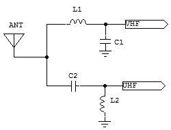
The best option is to use a simple Diplexer made by a LPF and HPF, providing in this way some isolation between transmitters, otherwise you get different coupling problems.
Increasing the number of poles of the filters, you get better isolation.

2547920000_1393578471.gif
 

Status
Not open for further replies.

Similar threads

Part and Inventory Search

Welcome to EDABoard.com

Sponsor

Back
Top