Continue to Site

Welcome to EDAboard.com

Welcome to our site! EDAboard.com is an international Electronics Discussion Forum focused on EDA software, circuits, schematics, books, theory, papers, asic, pld, 8051, DSP, Network, RF, Analog Design, PCB, Service Manuals... and a whole lot more! To participate you need to register. Registration is free. Click here to register now.

Turn on a secondary circuit at a certain voltage?

Status
Not open for further replies.

jsmith24

Newbie level 6
Joined
Jun 25, 2007
Messages
14
Helped
0
Reputation
0
Reaction score
0
Trophy points
1,281
Activity points
1,394
Hi all,

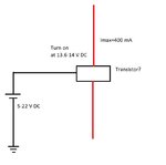
I'm setting up a small solar panel to act as a trickle charger for a small 12V SLA battery. I've stepped down the 22 volt max from the 1.5 watt solar panel to 13.5 volts with a buck converter, with a maximum current of about 250 mA, but when the solar panel outputs less than 13.5 volts, the buck converter starts drawing power from the battery I want charged. I tried simply placing a diode after the buck converter, but there is still reverse leakage current. What I'd like to do is have the circuit after the buck come on ONLY when the voltage coming INTO the buck exceeds 13.5 volts or so. I know that charge controllers are available, but a 1.5 watt panel doesn't output enough to drive a controller AND charge a battery.

So, I think it can be done with a transistor, I'm just foggy - been out of the game for way too long. Can anyone take my simple diagram and show me some magic? :) The simpler, the better!

Thanks,

Jack

circuit.jpg
 

A simple relay will do you a magic
 

A simple relay will do you a magic

I know, however, it would require more current than a transistor, and I'd still need a way to have it come on only over 13.5 volts or so.
 

If the input to the buck converter is less then the magic 13.5V, why not switch it off electronically, i.e. mute the oscillator? One problem I can see is at night when Vbattt is say, 12V and Vsol is 0V, your diode is required to stop the battery feeding volts into the output of the converter which it might not like.
Frank
 

I'm not sure the buck converter is the ideal solution because it will not buy you any benefit over a linear LDO regulator. To optimize the charging you really need to extract most energy from the PV whatever the voltage, even if it drops below your battery voltage. You need MPPT do do that.

The simplest, although not optimal solution is to use a PB137 three terminal regulator, it is purpose designed to charge SLA at the correct 13.7V and already has reverse discharge protection built in.

Brian.
 
Since the voltage between the battery and the charger is both negative and positive you can't do it with any type of transistor. In anyway, diode leaks less than a transistor.

The buck needs at least 3V to work with, it means that it will stop charging when the solar voltage drops to 17V, you wont get any charge on days without full sunshine. To my opinion you should take betwixt advice and use linear charger, that will charge when the solar voltage is down to 15V. You may get more efficiency this way depending on how sunny it is in your area.

If you can rewire your solar panel to have half the voltage (11V) and use boost inverter then you will get the max efficiency.


Okay, Vbase and betwixt - I really like the idea of the PB137 linear regulator. I just went with the buck because I knew I had to drop the voltage and that's the only thing I had in my bag-o-tricks at the time!

My panel is a preassembled cheapo unit, so I gotta take what it gives me, though.

So, the PB137 - is there a specific circuit for this, or do I just wire it inline like I would a standard voltage regulator? Another reason I went with the buck is because as it stepped down the voltage it increased the current: Is going with the linear regulator going to "waste" current?

Thanks, guys, this gives me hope.

Jack
 

Indeed they do 'waste' the excess power but you may be able to live with that. The PB137 works just like a conventional regulator, in-ground-out but the voltage is set to 13.7V which is what you normally charge a 12V SLA to for maximum capacity. I have attached the data sheet which shows the schematic.

I'm afraid the buck converter may not work as well as you anticipated. It is a more efficient way of dropping the voltage but PV panels are strange creatures and it isn't safe to see them as a simple voltage source. Their highest output voltage does not correspond with maximum power output. The only way to make best use of the power they produce is to use an MPPT (Maximum Power Point Tracking) circuit that acts as a 'middle man' between the PV and the battery. It makes sure the PV sees the best load to produce most power (V * I) while converting that power to the best voltage and current to charge the battery. How they work is quite complicated and relies on the MPPT circuit constantly trying different conditions to see which works best. They can make a fascinating project but are not economical to build on a small scale.

Brian.
 

Attachments

  • PB137.pdf
    632.1 KB · Views: 84
If the output of the solar panel (Vsp) is 22V day and night then inverter will give you better efficiency.
If Vsp is 16V day and night then the inverter is off all the time and the efficiency is 0, PB137 will be better.
The efficiency depends on the average Vsp.
I and betwixt live in Europe and we know that Vsp is 22V only for a few hours a week. You can log the Vsp in your area and then decide.
If you choose inverter I will put in my note book that you live in the Mohave desert.:)
 
Last edited:
Indeed they do 'waste' the excess power but you may be able to live with that. The PB137 works just like a conventional regulator, in-ground-out but the voltage is set to 13.7V which is what you normally charge a 12V SLA to for maximum capacity. I have attached the data sheet which shows the schematic.

I'm afraid the buck converter may not work as well as you anticipated. It is a more efficient way of dropping the voltage but PV panels are strange creatures and it isn't safe to see them as a simple voltage source. Their highest output voltage does not correspond with maximum power output. The only way to make best use of the power they produce is to use an MPPT (Maximum Power Point Tracking) circuit that acts as a 'middle man' between the PV and the battery. It makes sure the PV sees the best load to produce most power (V * I) while converting that power to the best voltage and current to charge the battery. How they work is quite complicated and relies on the MPPT circuit constantly trying different conditions to see which works best. They can make a fascinating project but are not economical to build on a small scale.

Brian.

Okay, I think I see. From what I've read, MPPT and other charge controllers just won't work with small panels like mine. The only reason I got the panel was to keep a 9AH SLA topped off. The battery powers an automatic opening/closing chicken coop door that I built for a local family. The door project itself was pretty straight-forward, and is fairly low draw: pulls 220 mA for 15 seconds, twice a day, plus just under 5 mA for about 12 hours a day. The 220 is the 12V motor opening/closing the door, the 5 mA is the current that the timer-relay switch uses to hold the door in it's "up" state. I had looked for a way to cut out the 5 mA by using some sort of electro-mechanical toggle switch, but I gave up on that idea and just decided I'd try to keep the battery topped-off. The coop is out in some woods, no AC mains line, gets decent sunlight, so I tried to use what I had. :)

Hey - I'm open to any useful, low-cost suggestions! Hmm...I wonder - if I can get my hands on a PB137 and put it in between the buck and the battery (say, 15-17 volts from buck), that might keep some of my current. I know it's not MPPT, but might be a decent enough solution; at least it might prevent the family from having to pull the battery and tote it back to the house to charge so often.

Thanks, betwixt!

- - - Updated - - -

If the output of the solar panel (Vsp) is 22V day and night then inverter will give you better efficiency.
If Vsp is 16V day and night then the inverter is off all the time and the efficiency is 0, PB137 will be better.
The efficiency depends on the average Vsp.
I and betwixt live in Europe and we know that Vsp is 22V only for a few hours a week. You can log the Vsp in your area and then decide.

I'm in Richmond, Virginia (US), and from now until mid-to late August, we get a lot, and I mean a LOT of direct sunlight. On the last three days of testing outdoors, I'm getting 18-22Vsp for the majority of the day, even without changing the angle of the panel.

I'm not sure I followed your thoughts on the inverter vs. the regulator, though...

- - - Updated - - -

Update: I was wrong in my post: It takes 35 mA to keep the door up for 12 hours.

Jack
 

If you like to do some development you can use this circuit that I learnt from an engineer in the mother firm in Rochester NY , some years ago.
It's a crude switcher that in low load current turns into linear regulator.
The way it works:
On load current over 30mA , Vbe/22R, the PNP transistor is on. The current in the coil ramps up and turns up the voltage of the 100uF. Because the output of 317 goes up the regulator switches off , no current into the input of 317 switches off the PNP. When the cap voltage falls the 317 switches on again.
Select PNP TO220 for 5A with high gain.

https://obrazki.elektroda.pl/8207440100_1431110291.gif
 
The amount of insolation depends largely on your latitude. Richmond is around 37N, Vbase is somewhere between 42N and 50N (I'm not sure where in France they are so that's the whole country!) and I'm way up north at 52.5N so I lose out on the sunshine :-( I still manage to pull a few KW from PV panels though but they are quite big.

The power capacity is difficult to calculate exactly but based on my experience with PV and battery equipment, I would think the PB137 alone gives most 'bang per buck'. If you start combining different technologies you also combine their losses and inefficiencies. At a pinch, if you can't get a real PB137 you could fake one with an LM137 and series diode or use a variable LDO regulator but the cost and complexity spirals upward quickly. MPPT works with any size of PV, the reason it is only used in larger installations is to do with cost effectiveness, in a small system its benefit would never be recovered financially.

Your 9AH battery if fully charged at the beginning should last about 10 days without recharging. The load is (12 * 0.035) = 0.42W which leaves around 1W left to put in the battery for later. That gives you about 2 hours of battery usage for each hour in sunshine while also holding the door open. You are cutting it fine, especially in winter and poor weather when the full PV power will be compromised. It will work but you could really do with a bigger PV panel to guarantee operation during prolonged bad weather.

Brian.


Thanks, Brian. I knew I'd be cutting it close, but the numbers I gave are worst-case scenario (plan for the worst, hope for the best, right?). I really appreciate your input, especially when combining technologies and their faults as well. I agree about MPPT - it's just not cost effective for a chicken coop. :)

Thanks!

Jack
 

If you like to do some development you can use this circuit that I learnt from an engineer in the mother firm in Rochester NY , some years ago.
It's a crude switcher that in low load current turns into linear regulator.
The way it works:
On load current over 30mA , Vbe/22R, the PNP transistor is on. The current in the coil ramps up and turns up the voltage of the 100uF. Because the output of 317 goes up the regulator switches off , no current into the input of 317 switches off the PNP. When the cap voltage falls the 317 switches on again.
Select PNP TO220 for 5A with high gain.

https://obrazki.elektroda.pl/8207440100_1431110291.gif

Thanks! That will give me something to experiment with while I'm waiting on the PB137 to arrive in the post!

Jack
 

I live in NW France which has similar climate to Wales.
Jack, I hope you sympathize a little.


I do! It gets much too warm here for my taste, I prefer the cold, though. :)
 

Hey betwixt (Brian),

I received my PB137, but have a general knowledge type question for you. When the input voltage drops below the dropout voltage of around 15.7-16 Volts, does that mean that the regulator shuts down, gives a 0 Volt output? If that's not the case, and it still provides some voltage, will it begin it's "reverse state" and not allow the battery to discharge? I've looked at the datasheet, but I'm not sure I'm reading the graphs correctly.

Other folks can chime in as well...

I think I just attached the datasheet. If not, this is the link: https://www.farnell.com/datasheets/1767487.pdf
Thanks,
Jack
 

Attachments

  • pb137.pdf
    664.2 KB · Views: 64

The PB137 stops being a constant voltage regulator when it can no longer sustain 13.7V at it's output, instead it looks like a resistor and limits the current it can pass into the battery. In other words it puts a ceiling on the voltage to protect the battery from overcharge but otherwise, if possible, it trickle charges it.

When it's input voltage drops below the battery voltage, "reverse state" it blocks current almost entirely so the battery will not discharge back into it. This is why I suggested that device, it doesn't need any aditional circuitry to block reverse flow.

Brian.

Thanks again, Brian! A wealth of knowledge!

Jack
 

Status
Not open for further replies.

Part and Inventory Search

Welcome to EDABoard.com

Sponsor

Back
Top