Continue to Site

Welcome to EDAboard.com

Welcome to our site! EDAboard.com is an international Electronics Discussion Forum focused on EDA software, circuits, schematics, books, theory, papers, asic, pld, 8051, DSP, Network, RF, Analog Design, PCB, Service Manuals... and a whole lot more! To participate you need to register. Registration is free. Click here to register now.

[SOLVED] Try to improve LM35 error question

Status
Not open for further replies.

d123

Advanced Member level 5
Joined
Jun 7, 2015
Messages
2,505
Helped
494
Reputation
992
Reaction score
525
Trophy points
1,393
Location
Spain
Activity points
27,148
Hi,

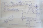
The LM335 has an adjust pin and you can calibrate out any error with a trimpot. The LM35DZ has no adjust pin and has an error range of up to 2ºC. From the schematic, does it look feasible to improve on any error by adding a trimpot from the Vout pin to ground, maybe set to a similar ratio as R2 and 0.125 R2? Would this ad hoc adjustment just scale with temperature rise to add additional error, creating a greater deviation from the original device slope, like with op amp gain? A resistor to ground to subtract the error +6 to +20mV (+0.6 to +2ºC) would scale with temperature, I think. Placing a small resistor from the ground pin to circuit ground to add a few mV if the error was -6mV to -20mV would also be unhelpful for the same reasons, would it?

imagen_2020-10-19_135347.png


Thanks.
 

Before getting into such fine detail, can you first explain what you are going to do with the voltage.
If you are going to digitize it, there is a much simpler solution that corrects for offset and gain using a simple mathematical formula. I have a system here that measures five analog temperature sensors, using 'raw' voltages gives up to 2C error but after the simple math it drops to 0.05C.

Brian.
 
  • Like
Reactions: d123

    d123

    Points: 2
    Helpful Answer Positive Rating
Hi Brian,

I'm hoping to use the LM35 output as a temperature-based voltage reference and to trigger a comparator at ~85°C.

Doubt you'll want to take this one seriously: I'm trying to emulate an LED's SOA curve (based on the datasheet graoh) - as best as I could hope to - with analog components. It's more a learning circuit than a sub-circuit worth adding to a torch circuit that already had a variable voltage reference for the constant current source op amp I am working on as it is a lot of extra components.

It's a digression from actual circuit just to resolve objective with analog parts.

Even so, I would be interested in knowing your digital solution as no matter how much I really love analog design, I need to start to learn how to use MCUs for all the reasons anyone knows are obvious when you compare both approaches and the pros and cons either offer.

Schematic and LED SOA graph attached.
 

Attachments

  • _20201019_162953.JPG
    _20201019_162953.JPG
    1.5 MB · Views: 76
  • White LED If vs Tamb Graph.JPG
    White LED If vs Tamb Graph.JPG
    26.7 KB · Views: 107

The SOA is subject to other thermal considerations, it isn't a graph of expected temperature at different currents, it to limit the allowed current at different die temperatures.

Calibrating temperature sensors, and to some degree the analog measuring circuits is quite easy after the 'raw' voltage has been converted to numbers. The method I use is 'two point compensation', basically you use four values, one pair is the theoretical value and measured value at one end of the temperature range, the other pair is the same at the other end of the range. By range I mean the upper and lower temperatures you are expecting rather than the limits in the data sheet.

The difference between theoretical and actual values give you the absolute error. You get an error value for each end of the range.
The difference between error values gives you the gain error.

Then for each measurement you take, multiply it by the gain error and subtract the absolute error. Fairly simple math.

Brian.
 
  • Like
Reactions: d123

    d123

    Points: 2
    Helpful Answer Positive Rating
Hi,

Digital solution:
* microcontroller
* digital (I2C) temperature sensor
* software

Klaus
 
  • Like
Reactions: d123

    d123

    Points: 2
    Helpful Answer Positive Rating
Status
Not open for further replies.

Similar threads

Part and Inventory Search

Welcome to EDABoard.com

Sponsor

Back
Top