Continue to Site

Welcome to EDAboard.com

Welcome to our site! EDAboard.com is an international Electronics Discussion Forum focused on EDA software, circuits, schematics, books, theory, papers, asic, pld, 8051, DSP, Network, RF, Analog Design, PCB, Service Manuals... and a whole lot more! To participate you need to register. Registration is free. Click here to register now.

Troubleshooting LTC3780 4 4-Switch Buck-Boost Controller

Status
Not open for further replies.

CaptainSpock

Junior Member level 3
Joined
Sep 27, 2011
Messages
27
Helped
0
Reputation
0
Reaction score
0
Trophy points
1,281
Activity points
1,475
Hi everyone

I reference this design from LTC3780 datasheet and made some adjustment to output a 12V/max current 4A from a input range of 5-15V. I build the circuit on a breadboard and tested with a input voltage of 5V but I am getting only 3.8-4V on the output. Can anyone enlighten me what's wrong with my circuit design? Any help will be very much appreciated

Screenshot 2016-09-18 13.09.43.png
Datasheet: http://cds.linear.com/docs/en/datasheet/3780ff.pdf

CaptainSpock
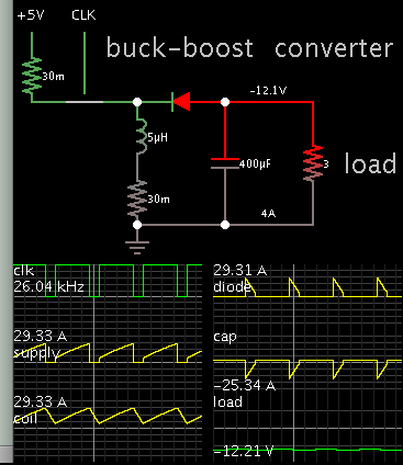
 

Your spec calls for 48W from a 5V supply. This winds up requiring that you draw peaks of 30A. The smallest parasitic resistance has a drastic effect on performance.

For the fun of it I am running a simulation. It has 0.07 ohm. The switch is set to 1/100 ohm.

1957188500_1474229804.png
 

thanks for replying

4A is set as the max current but I connected a load of 330ohm it still gave me an output of 3.8V. Is there something wrong I did there setting my current limit for this controller?

CaptainSpock
 

The buckboost inverts polarity. Is the LTC3780 able to interpret the negative polarity of feedback from your output?

Sorry, I have not worked with control IC's such as the LTC3780.
 

The buckboost inverts polarity. Is the LTC3780 able to interpret the negative polarity of feedback from your output?

Sorry, I have not worked with control IC's such as the LTC3780.

It is supposed to as that's the standard connection provided in the datasheet, the feedback should be able to detect voltages above or beloww the targeted voltage.
 

Hi,

I build the circuit on a breadboard
A breadboard is not suitable to test high speed power switching circuits.
You don't gain any useful information with this circuit built on a breadboard.

Use LTSpice to simulate it. Then build a PCB and follow the layout considerations given in the datasheet.

Klaus
 

Actually that schematic have been simulated in LTspice. I still not very sure how is the current limit is set so I decided to build it on breadboard to investigate further. I followed the formula in the datasheet to set the max current for Buck and Boost mode but in the simulation it the output current ignores the max current that I set. Can someone explain to me how the circuit at Ith pin works? I have been reading the datasheet but they didn't explain how does it works.

CaptainSpock
 

Your schematic has several mosfets. I suppose these are operated to create either a buck converter sometimes, and a boost converter other times? In that case you always have positive output polarity.

All those mosfets need to be operated at exactly the proper times, and they need to be fully On and fully Off. It might help to replace certain mosfets with diodes or plain wires, so it gives you a simple buck converter. It's easier to do tests on that. Verify that the mosfet operates as it ought to. Try various loads. Verify that you get expected output voltage. Later re-arrange it into a boost converter, and do more tests.
 
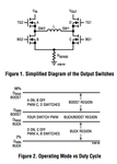
That's a great idea thanks. Yes the mosfets switching work as follows

Screenshot 2016-09-19 19.24.37.png

I will give your method a try and give a update over here

CaptainSpock
 

Status
Not open for further replies.

Similar threads

Part and Inventory Search

Welcome to EDABoard.com

Sponsor

Back
Top