Simon-Pedersen
Newbie level 2
Hello.
I have been given the task of designing a 3 stage 300 watt audio amplifier. The amplifier is suppose to contain a differential input stage, a voltage amplifying stage and a class AB output stage.
I have nailed the first and last stage, but can't seem to get the design of the VAS stage to work.
The design I am trying to achieve has the following specifications :
Given the fact that I know that there is 1 mA flowing through the collector, I choose the Resistor(RC) to be around 60 K, this ensures that when no input signal is applied to the VAS stage the output should be zero.
From there i calculated what the emitter resistance(RE) should be based on the following equation :
\[
\begin{equation}
AV =\frac{ \frac{RC*RL}{RC+RL}}{re+Re}
\end{equation}
\]
Only problem is that when i simulate the circuit using LTSPICE, i don't get a 1000V/V amplification at all, in fact i get an attenuation.
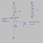
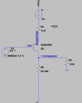
I have uploadede some pictures of my circuit and the input and output.
I Hope someone can point me in the right direction, i have been hammering at it all day,


I have been given the task of designing a 3 stage 300 watt audio amplifier. The amplifier is suppose to contain a differential input stage, a voltage amplifying stage and a class AB output stage.
I have nailed the first and last stage, but can't seem to get the design of the VAS stage to work.
The design I am trying to achieve has the following specifications :
- The operating point given from the differential input stage is 45 Volts, with a signal swing of 14 V
- A Collector current of 1 mA
- A overall VAS stage gain of 1000 V/V
- VCC+ and VCC- 60 V
- Delivering the output signal to a load of 100k ohms.
Given the fact that I know that there is 1 mA flowing through the collector, I choose the Resistor(RC) to be around 60 K, this ensures that when no input signal is applied to the VAS stage the output should be zero.
From there i calculated what the emitter resistance(RE) should be based on the following equation :
\[
\begin{equation}
AV =\frac{ \frac{RC*RL}{RC+RL}}{re+Re}
\end{equation}
\]
Only problem is that when i simulate the circuit using LTSPICE, i don't get a 1000V/V amplification at all, in fact i get an attenuation.
I have uploadede some pictures of my circuit and the input and output.
I Hope someone can point me in the right direction, i have been hammering at it all day,

