Continue to Site

Welcome to EDAboard.com

Welcome to our site! EDAboard.com is an international Electronics Discussion Forum focused on EDA software, circuits, schematics, books, theory, papers, asic, pld, 8051, DSP, Network, RF, Analog Design, PCB, Service Manuals... and a whole lot more! To participate you need to register. Registration is free. Click here to register now.

Trouble finding equivalent transistor to 2SC1162 and inductor uH

Status
Not open for further replies.

KiralyCraft

Newbie level 4
Joined
Sep 17, 2014
Messages
7
Helped
0
Reputation
0
Reaction score
0
Trophy points
1
Activity points
72
Hello there, i'm new here so please excuse me if i posted this in the wrong thread.
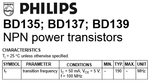
I am building an FM transmitter and ran into two problems. The circuit i designed uses a 2SC1162 transistor, but the specific one is unavailable in my country apparently. I have been looking for equivalents but with no luck so far. Thus i came here for suggestions.
My second problem is that i have to use a 1 cm diameter, 6 cm length, 7 turns of 18SWG wire, inductor. If i calculated right, the inductance is 7.5 uH. I would rather buy an inductor that works as expected, rather than building one myself with a chqnce of failiure. I am asking what kind of inductor should i get?
 

A 2SC1162 is a Japanese high frequency power transistor. A European BD135, BD137 or BD139 has the same package and will work the same.
The inductor is simply a few turns of wire and is simple to make. It will be about 100nH (0.1uH). I don't think anybody makes an inductor with such a low value.

The transmitter using a power transistor will probably produce enough output power to cause interference to people listening to FM radio stations, or interfere with aircraft communications if off frequency which is illegal in most countries. Most of these simple FM transmitters use an ordinary little transistor and produce fairly low output power.
 

The 2SC1162 is classed as a LF power NPN transistor with a "transition frequency" of 180MHz rated for 2.5A.

These would be the critical specs with some tolerance for lower currents and >150MHz for 100MHz operation. Everything else is optional but will have some effect.

You can wind your own coils with a coarse thread bolt and stiff wire and use online coil calculators to derive the N turns and diameter. The wire diameter can be same or less than thread spacing. The length can be the more or less than the diameter for suited for stiffness, depending on turns required. Magnet wire is preferred if coils are too close to touching.

Resonating a pulse with a small known capacitor and online cal, will tell you the inductance.
 

The 2SC1162 is classed as a LF power NPN transistor with a "transition frequency" of 180MHz rated for 2.5A.
I saw the English datasheet but I think the words "low frequency" is a bad translation from Japanese. A TIP31 has about the same output power at low frequencies but its fT is only 3MHz.
 

Thanks for your answers first, and secondly I found some transistors laying around. They are BD139, as you mentioned above. I am trying to build this scheme https://sites.google.com/site/ehobbyprojects/simple-and-powerful-fm-transmitter but for some reason my 22 pF trimmer burned out?! The guy at the components store asked my how many ohms should my trimmer have (which the scheme is lacking information). I bought 100 & 200 ones, not having a clue which i should get. When i built the circuit on the breadboard, my radio could only pick up signals around 108 MHz, no matter the capacitor. My next question is, why did the thing burn out, and am i doing this coil right? It should be 18SWG which is around 1.2 mm, but the only wire i could find was close to 1.8 mm.
Attaching images of coil & transistor.
DSC03438.JPGDSC03439.JPG
 

A 22pF trimmer IS NOT A RESISTOR, it is a low value adjustable capacitor.

What did you use for the 3.3pF capacitor?

The coil is WAY TOO BIG.
The coil on my FM transmitter and on hundreds of FM transmitters shown in Google is only 10mm (1cm) long and is 5mm (0.5cm) wide.

FM radio stations operate at VERY HIGH FREQUENCIES that do not work on a solderless breadboard because the capacitance and inductance between the many rows of contacts and wires is too high.

Here is a photo of a typical trimmer capacitor. They are made in many colors:
 

Attachments

  • trimmer capacitor.jpg
    trimmer capacitor.jpg
    10.2 KB · Views: 111
Last edited:

The size of your coil appears designed to carry several amperes. I thought it seemed unbelievable that you had to make it that large. Nevertheless it matches the ehobbyprojects article. So I guess it is intended.

As for the 22pF trimmer capacitor, its size also must allow it to carry several amperes.
There are little bitty trimmers a few millimeters wide. Then there are tuning caps a few inches wide.

Did you use a little bitty trimmer cap? That is why it burned out, no doubt.

I believe you need a larger tuning cap. They are rare nowadays. You may need to make your own. Such projects can be found on the internet.
 

If the voltage across the emitter resistor is 2VDC then the average current is 2V/33 ohms= 61mA. Its dissipation is only 1/8W so why is a 5W resistor used? In case it is connected directly and continuously to 12V?
If the collector of the power transistor swings from 12V to 2V then the tuned circuit swings it symmetrically up to 22V then its average voltage is 12V. The transistor heats with (12V - 2) x 61mA= 0.61W.
The output of 20V p-p is 7.07V RMS. The antenna is probably 75 ohms so the output power is 7.07V squared/75 ohms= 0.67W which is highly illegal in most countries.

The current in the coil and trimmer capacitor is peanuts.
 

BD139 is not recommended here because it is a general Purpose GP rated medium power transistor with no Spec for Transition Frequency, which I stated before is critical. You need at least 150MHz Try one of these, soldered to a copper ground plane.

Considering fT specs go up to 3GHz this is the highest end of a LF medium power transistor or lowest end of a High Frequency medium power device.
 

The output of 20V p-p is 7.07V RMS. The antenna is probably 75 ohms so the output power is 7.07V squared/75 ohms= 0.67W which is highly illegal in most countries.

The current in the coil and trimmer capacitor is peanuts.

I'm certain you are correct. Large voltage/ current is not needed. However it might conceivably build in the LC tank loop, under some conditions. Particularly if the antenna does not load the LC loop properly. Caused by impedance mismatch, untuned antenna, wrong length, etc.

I wonder if the ehobbyprojects fellow had this going on in his transmitter? So to handle it, he made the coil oversize?
 

BD139 is not recommended here because it is a general Purpose GP rated medium power transistor with no Spec for Transition Frequency, which I stated before is critical. You need at least 150MHz Try one of these, soldered to a copper ground plane.
That's true for recent datasheets. I have an old ITT databook where BD139 has a 250 MHz fT specification, which is well in the 2SC1162 range. I would expect a similar fT with newer BD139 types.
 

BD139 is not recommended here because it is a general Purpose GP rated medium power transistor with no Spec for Transition Frequency, which I stated before is critical. You need at least 150MHz.
No.
Whose datasheet did you look at?
I suspect that Philips invented the BD139 power transistor.
 

Attachments

  • BD139.png
    BD139.png
    16.8 KB · Views: 146

Yes i did indeed use a tiny trimmer capacitor, maybe that's why it burnt out. The coil seemed too big to me too. The 5W resistor seemed strange too, but i think it was used for continuous 12V load. All in all, should that diagram work? Using a BD139 as mentioned, a trimmer capacitor a bit bigger (or lowering thr voltage), and the coil designed for high amps? If not, what should i change in order for the circuit to work? Last plan would be choosing another scheme (suggestions please?). I followed this specific scheme because of the high power. I know it might be illegal, but i really need a high power FM tranismitter, just for the sake of learning. Im totally new to this kind of projects, that's why im asking here for help :D
 

I still don't believe that the "burnt-out" part was a capacitor. You didn't show a photo yet.
 

Most FM transmitters use a higher value for the 3.3pF positive feedback capacitor. Try 4.7pF and 10pF.
I have also never seen a capacitor that was "burnt out".
 

Sorry, my bad. I will give it a go with a 4.7 pf and 10 pf, but as for the capacitor here are some photos: DSC03442.JPG DSC03443.JPG . The first picture has both capacitors the store clerk sold me. One is "100 ohms" and the other is "200 ohms". This seemed very strange to me because a 22pf capacitor should not have an ohm rating? Oh well. The second picture shows the one that i used (the one said to be 100 ohms). You can see the plastic melted. That was the place where smoke started to come out from. But maybe it was a mistake on my side. Have i connected it properly? I used the one pin that is alone (in the right side of the 2nd picture) and one of the other two.
 

These are all trimmer resistors, not capacitors, as already assumed by others.
 

Are you implying that if i got actual trimmer capacitors, and maybe corrected the 3.3 pf value into 4.7 or 10, considering that im using that huge coil and the BD139, the circuit will work?
 

Personally, I would ban designs like that from the Internet.

KiralyCraft, we appreciate you are a beginner and sincerely trying to understand how it should work but looking at it from a more experienced position, the design, like many others on the Internet is very poor and will give terrible performance. Sadly, there are many electronics project sites that give the impression they are showing proven and reliable designs when in reality, they are demostrating what one person did with the parts they had available at the time. They are sometimes dangerous, rarely optimal and often work more by luck than design.

In your case the 'guy at the component store' clearly knows very little about what he is selling and has complicated your efforts by providing wrong parts, not only wrong values but wrong types of component altogether.

I suggest you forget this particular project and instead look for a more practical transmitter design. This topic pops up many times on Edaboard and I'm sure a search will turn up something more appropriate and with better prospects of working.

Brian.
 
Status
Not open for further replies.

Part and Inventory Search

Welcome to EDABoard.com

Sponsor

Back
Top