Continue to Site

Welcome to EDAboard.com

Welcome to our site! EDAboard.com is an international Electronics Discussion Forum focused on EDA software, circuits, schematics, books, theory, papers, asic, pld, 8051, DSP, Network, RF, Analog Design, PCB, Service Manuals... and a whole lot more! To participate you need to register. Registration is free. Click here to register now.

Transistors as amplifiers - limiting current but not voltage

Status
Not open for further replies.

unseen wombat

Newbie level 4
Joined
Aug 13, 2004
Messages
7
Helped
0
Reputation
0
Reaction score
0
Trophy points
1,281
Activity points
146
Hey guys, I know this is probably a really simple question, but I want to limit the current of my circuit's output to ~1mA, but not the voltage and I don't know how.

Let me explain what I'm doing. I'm building a Cranial Electrical Stimulation (CES) device, using an Atmel microcontroller, to use for lucid dreaming. I'm okay with the programming portion of it, and it's just handling the output that I need help with.

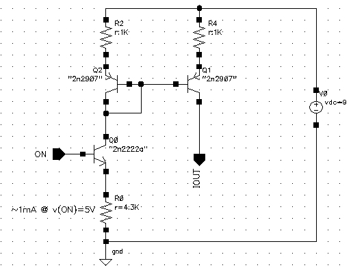
Here is a schematic of my design:

**broken link removed**

What it does is this: pins 2 and 7 of the IC just output square waves at a certain frequency. When 2 is high, 7 is low and vice versa. The two transistors directly left and right of the IC then amplify the 5V output to the battery's full 9 volts and leads from their emitters are attached to opposite ears. The other two transistors are there to short the other ear to ground and direct the 1 mA current through the person's head. So, for example, if pin 7 were high, pin 2 would be low. The red lead in the schematic going to the left ear would send 9 volts, the green lead coming from the right ear would short to ground and complete the circuit. The green lead attached to the left ear is shut off, because pin 2 is low, preventing a short circuit right at the left ear. Does my logic make sense?

Anyway, I thought I would just need a resistor attached to the collectors of the output transistors to limit the current to 1mA and the voltage would still be 9V, but as I'm sure you all know, that didn't work. I got about .03 V and up to 50 mA depending on the size of the resistor. So what do I need to do to get 1mA at 9V? Do I need a capacitor in there somewhere? Oh, the transistors are NPN 2N2222's and the battery is a 9V alkaline if it makes any difference.

Thanks for your help.
 

Are you trying to build an electric chair? :)

Couple of comments: You are not going to be able to amplify using a voltage-follower (input at base terminal, output at emitter) configuration. Also, a 5V signal is extremely large for any transistor the way you are trying to use it.

Have you looked into using opamps configured as buffers instead of single transistors?
 
Re: Transistors as amplifiers - limiting current but not vol

alfredop said:
Are you trying to build an electric chair? :)
lol no. Apparently 1mA is sufficiently small according to the research that it doesn't do any harm to a person.

Couple of comments: You are not going to be able to amplify using a voltage-follower (input at base terminal, output at emitter) configuration.
I don't understand, why not? I thought you input a small signal at the base, and get a large signal at the emitter. Isn't that how transistors work?

EDIT: Wait, I'm so stupid. I need to rig it up as a "common-emitter amplifier," don't I?

Also, a 5V signal is extremely large for any transistor the way you are trying to use it.
Yeah, I know. I had 10k resistors attached to the base, but then saw that the datasheet said it could take up to 6V.

Have you looked into using opamps configured as buffers instead of single transistors?
The only reason I like to stay away from op amps if possible is they're big. Compared to a transistor anyway, and I'd like to keep the unit in as small a package as possible, because it'll be used while I sleep. I'd also like to keep the wiring as simple as possible. I don't know, maybe it's not as big a problem as I think.
 

Hi unseen wombat,
You can take OpAmps (over up to 10 years) in same small package as SMD transistors_ca. 2x2.5 mm!:)
How big can be your electronics box pls?
Maybe you can drown a voltage diagram_for the 4 signal electrodes, what the situation is, what you need on all 4 electrodes to the same time and so on...
K.
 

A common-emitter configuration will do a much better job amplifying. Make sure to take your output signal from the drain terminal. :)

Now, how are you setting the operating point (biasing) of your transistors? Your schematic doesn't show a biasing network either.
 

Re: Transistors as amplifiers - limiting current but not vol

Perhaps you want to make a "rack" of current mirrors like so:
That's something I've never seen before. Shows you how much I know about electronics. :p So IOUT is the lead going to one ear, right? And it's 1mA at 9V? That's exactly what I want. Is there perhaps a simpler way to do it though? with fewer components if possible?

Now, how are you setting the operating point (biasing) of your transistors? Your schematic doesn't show a biasing network either.
lol wut? Seriously, I don't know anything about biasing. Let me look it up.

Okay, you're talking about using resistors at the collector and the base, right? I think I understand, but I don't know how to determine the sizes. What is the "operating point" of a 2N2222?

Back to the original question: Wait a second, suppose I put a resistor in parallel with my head. (lol that sounds so silly). Wouldn't that drain some of the current, and depending on the size of the resistor, I should be able to get the output current down to ~1mA, with the voltage remaining at Vcc, so it would look like this:

**broken link removed**

Amirite? Can I keep the voltage follower set up with the outer transistors since they're only shorting to ground when the opposite ear's signal is being sent? Or do I need to do something else? Maybe they won't sink the full 9V in that set up. How would I set them up if that's the case?

Also, this is sorta relating to the digital portion of the project, but with this common emitter amplifier set up, I'd have to reverse what I was doing with pins 2 and 7 of the uC, right? So the signal would be high when the pin output was low.

Added after 1 minutes:

Oh wait, you said from the drain terminal. So I'd have to move the red leads and the current-splitting resistor to below the transistor? What's the purpose in that?
 

Wombat:

I would recommend that you take a couple of hours to review the lecture notes on bipolar junction transistors and the examples on BJT DC biasing and BJT Amplifiers in the link below:

https://www.ece.tamu.edu/~karsilay/ecen325/

If you have no background on electronics, think of DC biasing of a transistor as turning it "ON" before you can even start thinking about using it in a circuit.
 

Hi,
I think: transistor biasing is one subject and the question of needed signals to the head is another!
If unseen wombat tells; knowledge of research tells us= left ear has to become 1 mA end the right ear to the same time a "Zero" -or GND, then the rest is relative uninteresting...
You -we can give a circuit that delivers the conforming signals & he dont need understand the physics of transistors:)
But unseen wombat pls make an absolut clear declaration of your needed signals, that is reasen if I wrote: ls. sketch us a signal diagramm....

I think it is a relative simple circuit, with the current generators from dick_freebird, their current is simple to control/set for other values too ("programmable"), but the question over 9V is (in my opinion to vorget), if the healing signal is only a current from right to left ear and maybe in the opposit direction...
Am I right unseen wombat?
K.
 

In my sketch, the 2N2222 may be considered an "emitter
follower". This means the base voltage will be "followed"
by the emitter, at 1 diode drop below; base current will be
the emitter resistor current divided by hFE (figure 10uA or so)
and the collector current is pretty much equal to emitter
current, which is (base-0.7)/4.3K. Your uC ought to rail nicely
at that low a current. The upper mirror just turns the polarity
around and throws its image.

Emitter followers are "self-biasing" in a sense. You don't
really need deep understanding to "get it done".

These transistors ought to stand off 30V (BVceo) at least;
no worries there. Just don't avalanche the E-B junctions,
which will probably break at 7V and be drifted at about 6V
long-term. Not a problem, as-described.
 

Status
Not open for further replies.

Similar threads

Part and Inventory Search

Welcome to EDABoard.com

Sponsor

Back
Top