Continue to Site

Welcome to EDAboard.com

Welcome to our site! EDAboard.com is an international Electronics Discussion Forum focused on EDA software, circuits, schematics, books, theory, papers, asic, pld, 8051, DSP, Network, RF, Analog Design, PCB, Service Manuals... and a whole lot more! To participate you need to register. Registration is free. Click here to register now.

Transistor for bidirectional switching

Salvador12

Full Member level 4
Joined
Jul 16, 2014
Messages
206
Helped
3
Reputation
6
Reaction score
7
Trophy points
1,298
Activity points
3,950
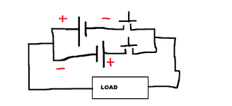
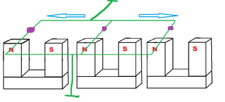
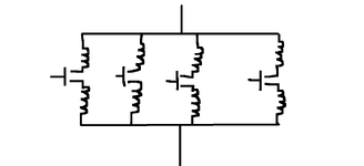
I have two coils where the start of each coil is connected together while the ending connected to a transistor that connects it then further to the circuit, I need to switch between the coils but in such a way that only one coil is ON at any time.
The problem is that each coil has opposite EMF and current direction, this means that as long as my voltage is very low (below the MOSFET body diode threshold voltage) I can get away with using just single FET for each switch, but if my voltage gets to above 1 volt and higher then the polarity of the coil that matches the MOSFET body diode will mean that FET will be always ON.

What can I use here ? One example I know is back to back series MOSFET's as a bidirectional switch but that complicates my design as it needs 2x more FET's and 2x more gates to control and most likely an IC for each back to back 2 FET switch.
Is there any other possibility with using just one switch/transistor for each coil?
 
There are probably many possibilities, but we need to know the whole story.
Let me be more precise,assume I have two batteries if I use just a single switch for each battery then I can only have batteries in "one " polarity, because if I oppose the polarity then my single mosfet conducts through the body diode.

Basically I need a switch that is bidirectional, controllable and can reverse block / not conduct current , so basically something like a Mosfet without a body diode, the voltages here are low anyway.
 

Attachments

  • mosfet problem.png
    mosfet problem.png
    22 KB · Views: 64
Let me be more precise
We would appreciate more precise information.
Like what voltage, what current, what other requirements (power, efficiency, ON-resistance, timing...) in values and units .. are you talking about?

We don´t necessarily need to understand the purpose (I can´t imagine what it is good for), but if we knew, we maybe could support you even better.

Klaus
 
I have two batteries if I use just a single switch for each battery
Sorry, but your schematic doesn't make sense for the two coils that are connected together.
Please show the whole circuit that you want, including the coils and where you want the switches.
 
We would appreciate more precise information.
Like what voltage, what current, what other requirements (power, efficiency, ON-resistance, timing...) in values and units .. are you talking about?

We don´t necessarily need to understand the purpose (I can´t imagine what it is good for), but if we knew, we maybe could support you even better.

Klaus
It is not a specific design, more of an idea in general for me to understand whether it can even work before I build it on a tabletop, therefore I do not have specs.

Look guys I'm sorry , I think I haven't been precise.
I'll try one more time as simple as I can.

What I have essentially is just a wire , and within that wire current reverses direction periodically so think of it as an AC current within a wire, this means that if I have a switch in the middle of the wire somewhere then for a single MOSFET it will be able to control current in one direction but in the other it will be continually ON due to it's body diode.

I know that one of the simple solutions is a two MOSFET back to back switch also known as a solid state relay, but that is twice the count of transistors + harder to drive , I was wondering is there any other option that uses just a single transistor?
 
I‘ll just add my voice to the others who are trying get you to present a schematic or a description that makes some kind of sense. Your latest “schematic” does, what? Maybe the H-bridge Dana showed is what you want, but it’s really hard to tell what you want.
 
I‘ll just add my voice to the others who are trying get you to present a schematic or a description that makes some kind of sense. Your latest “schematic” does, what? Maybe the H-bridge Dana showed is what you want, but it’s really hard to tell what you want.
basically I need a bidirectional switch,

Use a Triac. Bi-Directional Switch
I am starting to think that a common source series N fet arrangement could work for me, in either current direction the potential difference is then only across one of the two FET's , so in theory a simple drive circuit capable of giving 15 volts above the common source should be able to turn the FET's on when needed if both gates are tied together.
 
Ok , I updated an older drawing of mine that I posted here in a previous thread. This is the schematic, multiple parallel wires spaced equally apart , all parallel wires connected together at both ends. This forms equal loops which all share one of the wires as the common conductor which cancel out any eddy currents that would otherwise be generated in the loops as they passed the magnet field poles.
There is still a deflection current from Lorentz force that is formed in the parallel wires that traverse the field poles.
I am switching this current on and off as I need to, the switch is the violet dot shown on the wires.

each wire can be represented by a coil as it has some albeit small but inductance and capacitance, so the equivalent circuit would be a bunch of parallel coils being switched on off as DC current is flowing through them.
What happens with the back EMF in this case where does it go and where can I release it safely so that the switches don't get damaged?
Remember that only one switch is switched off at any time while the neighboring wire switches stay ON.
I also attached the equivalent circuit I drew.

My original question was about the switch to be used in this case.
AS for the flyback voltage given I don't have high voltage in the circuit, maybe I could just add some zener across the switch or other voltage limiter across the switch to discharge any excess voltage?

What about the common source back to back two N fet switch as used in solid state relays, IIRC, it should be able to discharge flyback voltage through the body diodes even when the fet's themselves are OFF?
 

Attachments

  • loop1.png
    loop1.png
    27.5 KB · Views: 57
  • parallel loop switching.png
    parallel loop switching.png
    18.3 KB · Views: 61
Has a switch to be triggered ??
i don’t know what that means, but I still wouldn’t use a triac here. You need to maintain a minimum current or the triac will turn off. But, considering the lack of useful information from the OP, maybe a triac is suitable.
 
Your description speaks of 2 inductors connected. Your first schematic shows two power supplies (2 batteries). And you wish to minimize parts count.
Perhaps a half-bridge suits the purpose?

Sample configurations. Alternate arrangement can have PNP at top, NPN at bottom.

half-bridge 2 barebones layouts with inductors.png
 

LaTeX Commands Quick-Menu:

Similar threads

Part and Inventory Search

Welcome to EDABoard.com

Sponsor

Back
Top