AdvaRes
Advanced Member level 4
Hi all,
I was reading the following paper:
https://ece.uwaterloo.ca/~cdr/pubs/maymandi/3.pdf.
I dont understand the transistor behaviour given by the relation (1) in the paper.
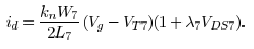
This equation is not for transistor in linear or saturation region. Could somebody explain this new expression and when we use it ?
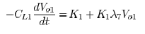
In a second step the autor try to calculate the voltage Vo using the equation (3).
And he say
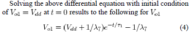
I applyed the laplace transform and than I applied the inverse laplace transform for the relation to calculate Vo(t). I found
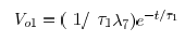
The result is different. I dont know what mistake I made in my calculation.
Could somebody help ?
Thanks in advance.
I was reading the following paper:
https://ece.uwaterloo.ca/~cdr/pubs/maymandi/3.pdf.
I dont understand the transistor behaviour given by the relation (1) in the paper.
This equation is not for transistor in linear or saturation region. Could somebody explain this new expression and when we use it ?
In a second step the autor try to calculate the voltage Vo using the equation (3).
And he say
I applyed the laplace transform and than I applied the inverse laplace transform for the relation to calculate Vo(t). I found
The result is different. I dont know what mistake I made in my calculation.
Could somebody help ?
Thanks in advance.