Continue to Site

Welcome to EDAboard.com

Welcome to our site! EDAboard.com is an international Electronics Discussion Forum focused on EDA software, circuits, schematics, books, theory, papers, asic, pld, 8051, DSP, Network, RF, Analog Design, PCB, Service Manuals... and a whole lot more! To participate you need to register. Registration is free. Click here to register now.

Transistor base current for this circuit ... Help

Status
Not open for further replies.

andro

Junior Member level 3
Joined
Nov 26, 2005
Messages
27
Helped
0
Reputation
0
Reaction score
0
Trophy points
1,281
Activity points
1,527
Hello
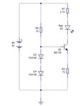
I have this simple current source circuit and the current source through the collector is controlled by voltage drop across the transistor base emitter and resistor R5
Ic=Ie = Vbe/R5

but i want to know how much current flowing through the base and diodes ?
The current flow through the resistor R6 = (9-1.4)/1K = 7.6mA
i supposed the total voltage drop across the diodes = 1.4
but how much current the diodes draw and transistor base for the transistor.
 

Attachments

  • diodecir.JPG
    diodecir.JPG
    10.7 KB · Views: 72

I think your estimate for current through R6 is pretty accurate. However, diode drop (ssumed 0.7V) is also slightly current dependent, so you should check on data sheet and re-iterate if you want to be very sure.

Regarding base current: It is quite small, but because it is dependent on hfe (the current gain) of the transistor It will vary aa lot depending if the transistor is in middle, on low side, or on high side of its wide range on the data sheet. There are even three different hfe -ranges for this transistor, covering current gains from 40 to 250!

As the base-emitter diode drop is likely about 0.6-0.8 V on small currents, the emitter current though R5 has to be such, that voltage over it is (2xdiode drop - Vbe) - in other words likely about 0.6V...0.9V. Assuming Vbe to be 0.7V, and diode drop being also 0.7V, the current would be about (2*0.7 -0.7)/70 A = around 10 mA.

And the base current? It can be then 10 mA divided with anything between 40 and 250, depending on the particular transistor. (For simplicity, I assumed here that collector and emitter currents are equal, as he difference is the base current, and that is always a small (hfe- ) fraction of the collector current.

Think and study carefully step-by step those voltages and currents, and you learn a lot about basic circuit analysis!
 

on transistor datasheet BD139 i have max rates , and from calculations as example i have ic= 10 mA
how can i extract the Hfe from datasheet according to my calculations, and in the datsheet there is min. values according to test conditions and there is typical characteristics but i am confused on how to extract the correct value.
 

but i am confused on how to extract the correct value.
The only way to find hFE for your BD139 is to measure it. It can be anywhere between the min and max given in the datasheet.

It is a good idea to design circuits so they work well with any value of hFE between min and max. This circuit is a good example. If Ic = 10mA, then Ib may be 10mA/40 = 0.25mA, or it may be 10mA/200 = 0.05mA.

As you calculated, current flow through R6 = 7.6mA, so current through the diodes may be 7.6mA - 0.25mA = 7.35mA, or it may be 7.6mA - 0.05mA = 7.55mA. The diodes don't care if the current is 7.35mA or 7.55mA. As long as the current through R6 is >> Ib, the circuit will work fine.

BTW, there is a problem with the load connected to the output of the current source. In theory Ic=Ie = Vbe/R5 = 10mA. However, that would mean the voltage drop across R7 = 10mA*2.7K=27V. That's impossible because the power supply is only 9V.

With the circuit as shown, hFE doesn't matter. The transistor is saturated, with Vce = about 0.05V.

Very rough calculation, assuming LED voltage = 1.7V:
Ie = 10mA
Ic = (9V - 1.7V - 0.7V) / 2.7K = 2.4mA
Ib = 10mA - 2.4mA = 7.6mA
current through diodes = 7.6mA - 7.6mA = about zero

If you made R7 higher than 2.7K, then Ie would be less than 10mA.
 
Last edited:
  • Like
Reactions: FvM

    FvM

    Points: 2
    Helpful Answer Positive Rating
Hi godfreyl

As your calculation on Ib= 7.6mA, you ignored the influence of the hFE and the value is big according if for example the hFE = 40 as min. value, the Ic would be 40*7.6 = 304 mA
 

As your calculation on Ib= 7.6mA, you ignored the influence of the hFE and the value is big according if for example the hFE = 40 as min. value, the Ic would be 40*7.6 = 304 mA

Youd should really read godfreyl's post more thoroughly. He explained why the transistor current gain doesn't come into play.
 
With the circuit as shown, hFE doesn't matter. The transistor is saturated, with Vce = about 0.05V.
I understood from your words if the transistor in saturation mode the hFE does not matter, but my simple question, how did calculated the Vce=0.05 V to know the transistor in saturation mode ?
 

The conclusion goes the other way around. Saturation is caused by external circuit, saturation voltage can be calculated from Ib and Ic.
 
Status
Not open for further replies.

Similar threads

Part and Inventory Search

Welcome to EDABoard.com

Sponsor

Back
Top