Continue to Site

Welcome to EDAboard.com

Welcome to our site! EDAboard.com is an international Electronics Discussion Forum focused on EDA software, circuits, schematics, books, theory, papers, asic, pld, 8051, DSP, Network, RF, Analog Design, PCB, Service Manuals... and a whole lot more! To participate you need to register. Registration is free. Click here to register now.

Transimpedance Amplifier using OPA 657 - Help needed ?

Status
Not open for further replies.

anas.ansarie

Junior Member level 3
Joined
Nov 3, 2011
Messages
29
Helped
3
Reputation
6
Reaction score
3
Trophy points
1,283
Activity points
1,468
Untitled.png

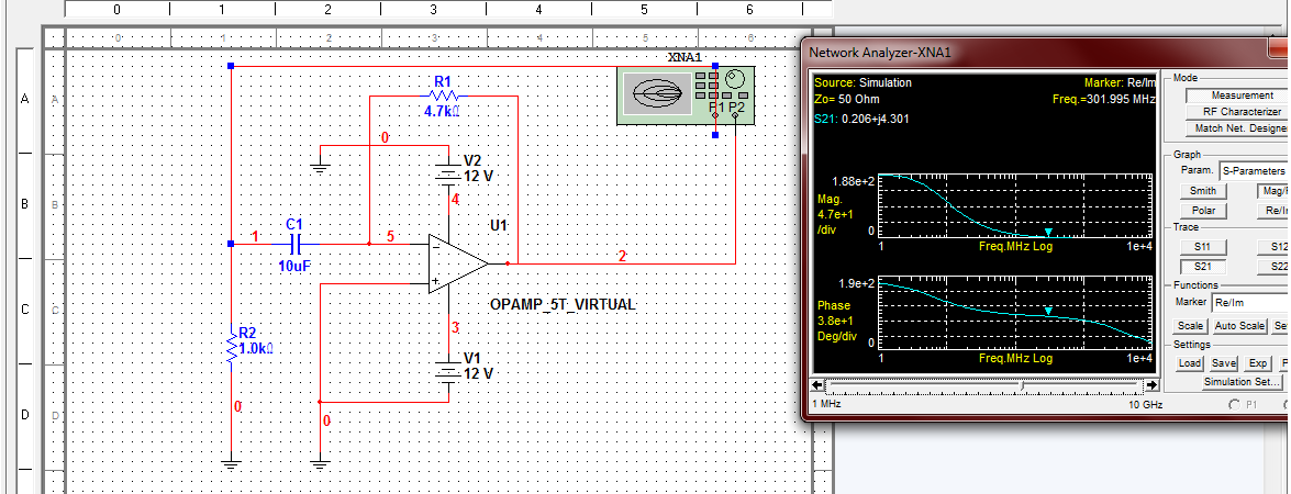
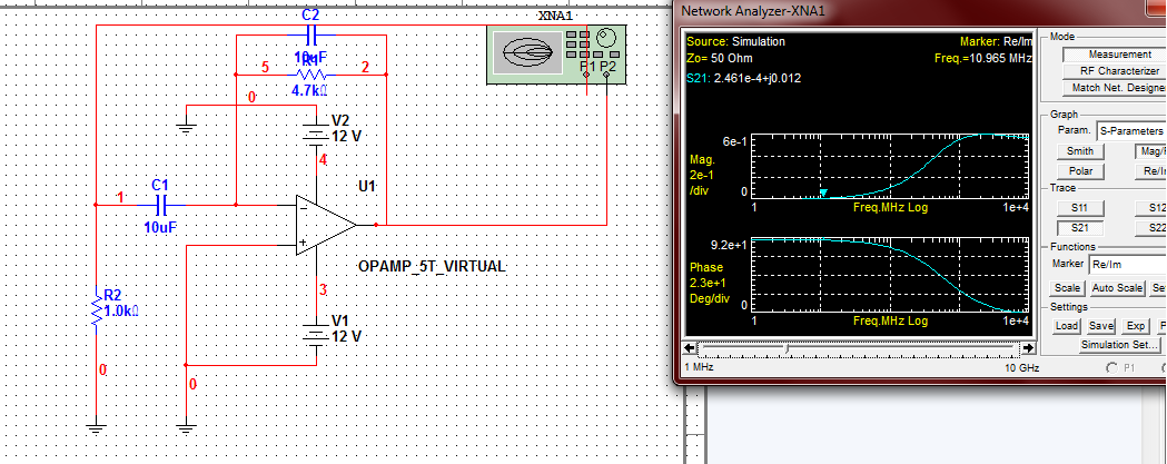
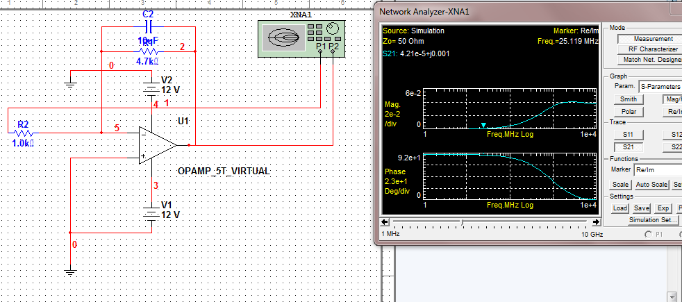
the opamp is OPA657 in transimpedance configuration. (attached above)

i wanted to ask if any one of you can tell me how is this amplifier acting, as Low Pass Filter, High Pass or Bandpass ... ?

could any one please tell me how to find this circuit's cut off frequency ?
 

High pass. AC response at the output of opamp is High pass in nature.
BandPass Filter ( simulation gives FL = 5Hz, FH = 2.3MHz for parasitic cap of 10pF) .
 

thnx varun

Bandpass ? how is it bandpass ? i have tried to simulate it in Multisim but it is telling that is high pass ?

would you please clear this problem ? plus i want to detect signals from this circuit upto 100 MHz ... will it be able to do so ?
 

band pass second corner frequency is set by parasitic cap. So depends upon parasitic cap you can increase your bandwidth up to 100MHz or more. Check the noise and other parameters.

---------- Post added at 11:57 ---------- Previous post was at 11:03 ----------

if you see transfer function there is one zero and one pole at the output of Amplifier. Which give High pass filter response.
Another pole with parasitic cap helps you to adjust your low pass filter pole.


These are some ov the results that i taken from multisim after simulation of that circuit ... can yu please help me whether they r correct or wrong ... ?

---------- Post added at 20:15 ---------- Previous post was at 20:05 ----------

band pass second corner frequency is set by parasitic cap. So depends upon parasitic cap you can increase your bandwidth up to 100MHz or more. Check the noise and other parameters.

---------- Post added at 11:57 ---------- Previous post was at 11:03 ----------

if you see transfer function there is one zero and one pole at the output of Amplifier. Which give High pass filter response.
Another pole with parasitic cap helps you to adjust your low pass filter pole.


Varun ... i tried to study literature regarding TIAs .... my photodiode capacitance is 2pF when reverse biased ... actually i want bandwidth of about 150 MHz ... Waitin for yur reply
 

As a first remark, OPA657 isn't unity gain stable. Unfortunately none of your configurations will result in stable amplifier operation.

Referring to the virtual OP simulations in post #5, the corner frequency created by the RC time constant is below the plotted frequency range, so you are unable to see a low- or high-pass effect. I suggest to perform elementary hand calculations to understand what you are doing here, or extend the frequency range to at least 1 Hz.

FvM .... i tried to do hand calculations too given in application note of OPA657 as TIA .... i found that Rf should be in pF as my photodiode has 2pF capacitance but the problem is

the above circuit is used by students of georgia tech in FSO receiver and they showd results ... im curious as how they have achieved such results ?

Plus would yu plz recommend me some literature on TIA with equations given ?

---------- Post added at 20:58 ---------- Previous post was at 20:51 ----------

As a first remark, OPA657 isn't unity gain stable. Unfortunately none of your configurations will result in stable amplifier operation.

Referring to the virtual OP simulations in post #5, the corner frequency created by the RC time constant is below the plotted frequency range, so you are unable to see a low- or high-pass effect. I suggest to perform elementary hand calculations to understand what you are doing here, or extend the frequency range to at least 1 Hz.

FvM .... i tried to do hand calculations too given in application note of OPA657 as TIA .... i found that Rf should be in pF as my photodiode has 2pF capacitance but the problem is

the above circuit is used by students of georgia tech in FSO receiver and they showd results ... im curious as how they have achieved such results ?

Plus would yu plz recommend me some literature on TIA with equations given ?
 

A standard TIA circuit should

- omit R8 and C6
- change Cf to a value between 0.1 and a few pF, depending on the photodiode capacitance.

As mentioned, stability with OPA657 is a special issue, it requires the feedback factor to be below 1/7.
 

    LvW

    Points: 2
    Helpful Answer Positive Rating

    Sky5

    Points: 2
    Helpful Answer Positive Rating
    V

    Points: 2
    Helpful Answer Positive Rating
Status
Not open for further replies.

Part and Inventory Search

Welcome to EDABoard.com

Sponsor

Back
Top